Safety & Responsibility
Electrical troubleshooting begins with safety. Before any diagnostic process, confirm that work can be performed without exposing yourself or others to unnecessary risk. This is not a formality — it is the foundation of every action taken on a job site.
Core Safety Rule
Treat every circuit as energized until you have personally verified otherwise with a calibrated meter at the specific work location. Not at the panel — at the work location. Panel labels are unreliable. Breaker position is unreliable. Another person’s word is unreliable. A meter reading at the point of work is the only acceptable confirmation.
Lockout / Tagout (LOTO)
LOTO is the process of isolating an energy source and physically preventing re-energization while work is in progress. The four steps are always the same: identify and shut off the correct circuit, apply a personal padlock through the breaker’s lock-off point, hang a danger tag with your name and date, then verify zero voltage at the work location with a calibrated meter. Only remove the lock when all work is complete and the area is clear. In commercial environments LOTO is required by OSHA 29 CFR 1910.147. In residential work the physical risks are identical — apply the same discipline.
Why Shock Is Dangerous
Severity depends on current through the body, not voltage alone. At 10 milliamps muscle contraction prevents releasing grip. At 100 milliamps ventricular fibrillation becomes likely. A GFCI trips at 5 milliamps — specifically because it interrupts current before reaching the fatal threshold that a 15A breaker would never respond to. When testing live circuits, keep one hand in your pocket or behind your back to reduce the risk of hand-to-hand current crossing the heart.
Meter Verification — Every Time
A dead meter shows zero on every measurement. The two-point check prevents this from becoming a fatal mistake: test on a known live source first, take your measurement, test the known source again. This takes 30 seconds and confirms the meter is working before and after your critical reading. Also inspect leads before every use — cracked insulation is a direct shock hazard — and ensure the meter is in the correct mode (AC voltage for live circuits, never resistance or continuity on energized conductors).
Personal Protective Equipment
Safety glasses are the minimum for any electrical work. Add Class 00 insulated gloves (rated 500V) when working near energized conductors. Arc flash-rated PPE is required when working inside an energized panel — the panel can remain energized even with the main breaker off, because the service conductors feeding them are controlled by the utility, not by anything inside the building. Use insulated tools with handles rated for the voltage category whenever working near energized components.
How Electrical Systems Fail
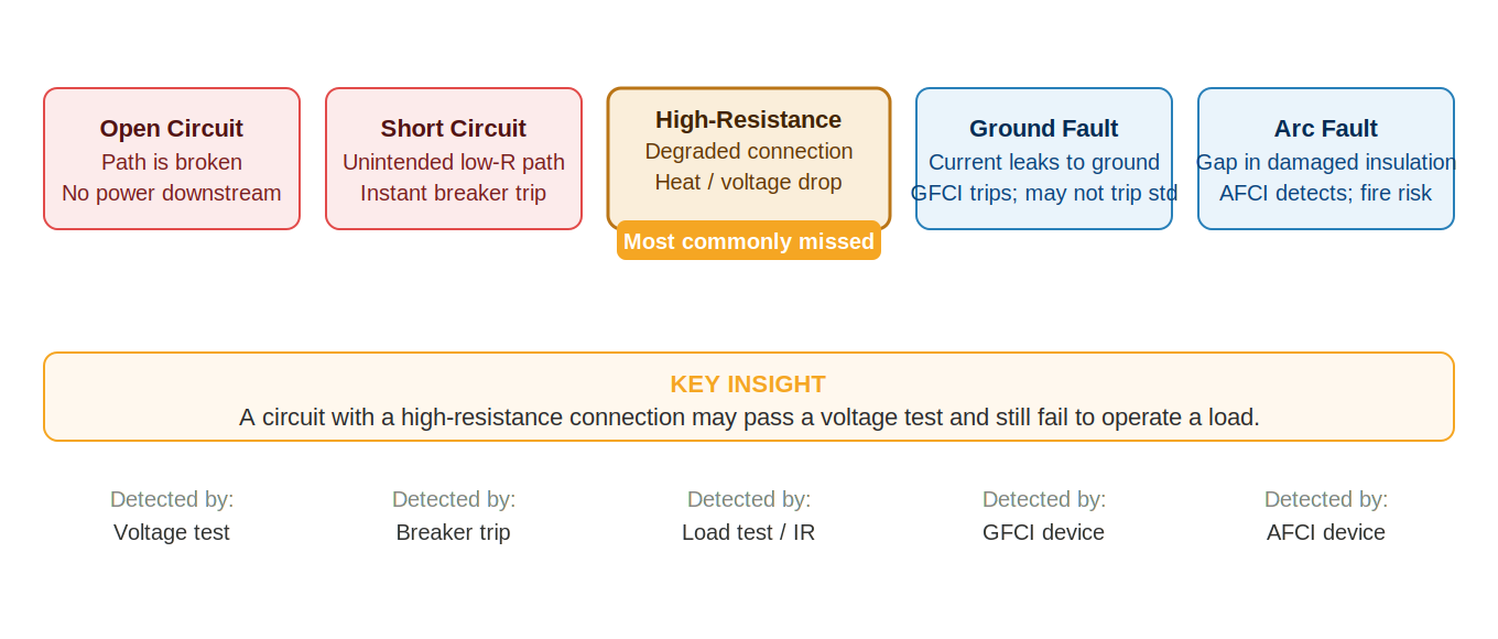
All electrical problems trace back to one of five failure types. Recognizing which type you are dealing with before you start testing saves time and prevents misdiagnosis. Each type produces a different pattern of symptoms and calls for a different testing approach.
Open Circuit
An open circuit is a complete break in the electrical path. Current cannot flow, so everything downstream loses power simultaneously. Common causes include a broken conductor, a wire that has pulled out of a terminal, a failed splice, or a tripped breaker that has disconnected the circuit.
Open circuits are usually the easiest failure type to confirm — voltage testing will show power on one side of the break and none on the other. The binary search method locates them efficiently. What makes them tricky is that the break can be anywhere along the path, including inside a device you wouldn’t think to open.
Short Circuit
A short circuit occurs when current finds an unintended low-resistance path — typically hot to neutral or hot to ground without passing through the load. The result is a sudden surge of current far exceeding the breaker’s rating, causing an immediate trip. In most residential circuits, a hard short will trip the breaker in milliseconds.
Diagnosing a short circuit: de-energize the circuit, disconnect the load, and test resistance between hot and neutral. A very low reading (near zero ohms) confirms a short somewhere in the wiring. Isolate by disconnecting sections until the short disappears, then inspect that section.
High-Resistance Connection
A high-resistance connection is a degraded connection that is still electrically present but no longer able to carry current effectively. This is the most commonly missed failure type because a no-load voltage test will often read normal — the problem only appears under current.
High-resistance connections develop through several mechanisms: thermal cycling loosens terminals, oxidation builds up on aluminum conductors, backstab spring contacts fatigue, and improperly torqued screws vibrate loose over time. The connection creates heat, which accelerates further degradation — a slow failure that gets progressively worse.
Symptoms include voltage drop under load, warm or discolored receptacles, flickering lights when a load switches on, and circuits that work fine under light use but fail under full load. Always test under load when this failure type is suspected.
Ground Fault
A ground fault occurs when current flows to ground through an unintended path — through damaged insulation, through moisture, or through a person. The current imbalance between hot and neutral is what GFCI devices detect and respond to, tripping at as little as 5 milliamps.
A critical safety point: a ground fault that causes 5mA to flow to ground will trip a GFCI but will not trip a standard 15A or 20A circuit breaker. This means a ground fault can persist indefinitely on an unprotected circuit — creating an ongoing shock hazard — without any protection device responding. This is why GFCI protection is required in wet locations regardless of breaker type.
Arc Fault
An arc fault occurs when current jumps across a gap — through damaged insulation, at a loose connection, or through a pinhole caused by a nail or staple that has penetrated the cable. Arc faults are intermittent and often cannot be located by standard voltage testing because the arc only occurs under specific conditions of load, vibration, or temperature.
Arc faults are serious fire hazards. An arcing connection can ignite the surrounding insulation and wood framing without ever tripping a standard breaker, because the peak current during an arc is not necessarily high enough to exceed the breaker’s trip threshold. AFCI devices detect the characteristic waveform pattern of electrical arcing and respond to it.
When an AFCI trips, the correct response is never to bypass it. The device is doing exactly what it is designed to do — find and fix the arc source.
The most dangerous failures are not always the most obvious ones. A hard short trips a breaker immediately and announces itself. A ground fault on an unprotected circuit and an arc fault developing inside a wall can persist for weeks without any visible indication — until something catches fire or someone is injured.
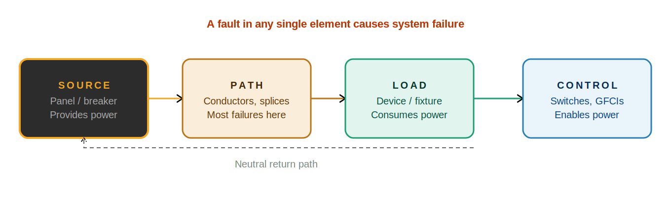
The Four Elements Model
Every electrical system — from a single lamp circuit to a whole-home automation installation — can be analyzed using the same four-element framework. When you understand what each element does and what can go wrong with it, you always know where to look next.
Source
The source is where electrical energy enters the circuit. In residential work this is almost always a circuit breaker in a panel, which connects to the utility via the service entrance conductors and meter. The source has two jobs: to provide correct voltage and to supply enough current for the load without interrupting.
Source failures are more common than technicians expect. Breakers fail internally while appearing to be on. Bus connections loosen over time. The utility itself can have problems. Always verify the source first — it is the fastest test to perform and eliminates the entire downstream circuit from consideration if the source is bad.
Path
The path is every conductor, splice, terminal, and connection between the source and the load. This includes the hot conductor, the neutral conductor, the ground conductor, wire nuts in junction boxes, terminal screws on devices, and any connections inside panels or at fixtures.
The path is where the overwhelming majority of real-world residential faults occur. Conductors break, connections corrode, backstabbed devices fail, wire nuts come loose under thermal cycling. The path looks simple in theory — just wire — but in practice it includes dozens of potential failure points in even a short circuit run.
Load
The load is the device that consumes electricity to perform work — a light fixture, receptacle, appliance, motor, or any other end device. Loads can fail internally, but in residential troubleshooting, load failure is less common than path or source failure. The most important principle for load testing is to verify that the circuit can actually deliver power before concluding the load has failed.
A load that has failed is usually straightforward to diagnose — substitute a known good device and the circuit works. A circuit problem masquerading as a load failure is far more common and requires systematic testing to uncover.
Control
Control devices determine when and how power is delivered. Switches, GFCIs, AFCIs, dimmers, timers, occupancy sensors, photocells, and smart home devices all belong to this category. Each has specific enabling conditions — a state it must be in for power to pass.
Control failures produce symptoms that look identical to path failures: power is present at the source, but nothing operates at the load. The difference is that control failures are often the fastest to diagnose — a two-second check of switch position and GFCI reset status can rule them out entirely before you open a single box.
Applying the Model
The four elements define your diagnostic sequence. Before touching any wiring, answer one question for each element: Is the source delivering power? Can the path carry it? Is the load functional? Are all control conditions met? Each “yes” narrows the problem. Each “no” or “unknown” tells you where to test next.
In practice, context clues will often tell you which element to investigate first. A circuit that worked fine until a thunderstorm suggests a source issue. Intermittent flickering on one circuit suggests a path connection problem. A device that doesn’t respond when controlled remotely suggests a control issue. Let the symptom guide your starting point, but let the four-element model ensure you don’t skip a category entirely.
The four elements model is not a checklist to work through in order every time. It is a mental map that ensures you never miss a category. An experienced technician who jumps directly to the most likely element is still using this model — they have just learned which element fails most often in a given scenario.
Tools and Testing Strategy
The right tool used correctly produces reliable information. The wrong tool, or the right tool used incorrectly, produces misleading data that can send you in the wrong direction for an entire job. Tool selection and verification are not optional steps — they are part of every test.
Multimeter — Primary Diagnostic Tool
The multimeter measures voltage, resistance, continuity, and in many models, current. For electrical troubleshooting, voltage measurement is the most frequently used function. Key practices for multimeter use:
- Verify before every use. Use the two-point check: test on a known live source, take your measurement, test the known source again. A meter that fails mid-test would show zero everywhere — this catches it before you make a dangerous assumption.
- Inspect leads before every use. Look for cracked insulation, damaged tips, or loose connections at the probe body. A lead with compromised insulation is a direct shock hazard.
- Match the mode to the task. AC voltage for live circuits. DC voltage for battery circuits and some control systems. Resistance/continuity only on de-energized circuits — testing a live circuit in resistance mode will damage the meter and may cause injury.
- Use the correct CAT rating. Meters are rated CAT I through CAT IV based on the energy level of the circuits they are designed to test. For residential panel work, CAT III or CAT IV is appropriate. A CAT I meter at a panel is a safety hazard.
- Always measure hot-to-neutral AND hot-to-ground. These two readings together reveal far more than either one alone. A normal hot-to-neutral reading tells you the hot is present and neutral is returning. A discrepancy between the two readings is often the first sign of an open neutral.
- Test under load when possible. Many faults — particularly high-resistance connections — only appear when current is flowing. A no-load reading can be normal while a loaded reading shows significant voltage drop.
Non-Contact Voltage Tester (NCVT)
An NCVT detects voltage by sensing the electric field around an energized conductor without requiring direct contact. It is useful for quickly confirming that a conductor is live before opening a box, or for tracing which conductors in a bundle are energized.
The NCVT has two significant limitations that must be understood:
- Ghost voltage. An NCVT can detect induced voltage from adjacent energized conductors, even on a de-energized wire. This is called ghost voltage or phantom voltage. It is real enough to trigger the tester but cannot deliver current. Never rely on a positive NCVT reading as confirmation that a circuit is energized — verify with a meter.
- No current information. An NCVT cannot tell you whether a circuit can actually deliver power. It only indicates the presence of a voltage field. A circuit with an open neutral will show a positive reading on the hot conductor while being completely unable to operate a load.
Use the NCVT for quick reconnaissance. Confirm all findings with a calibrated multimeter before acting on them.
Low-Impedance Tester (Wiggy / Solenoid Tester)
A low-impedance tester places an actual resistive load on the circuit when measuring. This makes it immune to ghost voltage — induced voltage cannot drive meaningful current through the tester’s load, so the reading collapses to zero. When a standard meter reads voltage but a low-impedance tester reads zero, the voltage is phantom and the circuit is not energized.
Low-impedance testers are particularly useful when working in conduit with multiple conductors running together, where ghost voltage on de-energized conductors is common.
Clamp Meter
A clamp meter measures current flow through a conductor by sensing the magnetic field the current produces, without breaking the circuit. It is useful for confirming that current is actually flowing, measuring load current to identify overloaded circuits, and checking current on the shared neutral of an MWBC.
For Multi-Wire Branch Circuit (MWBC) diagnosis, clamp the shared neutral and measure current with both circuits loaded. On a properly phased MWBC the reading will be low (the currents partially cancel). On an improperly phased MWBC with both hots on the same leg, the reading will equal the sum of both circuits’ currents — indicating an overloaded neutral.
Circuit Tracer
A circuit tracer consists of a transmitter that connects to a circuit and a receiver that detects the signal. It is used to confirm which breaker controls a given circuit when panel labels are inaccurate or missing, and to trace circuit runs through walls without opening them.
Circuit tracers save significant time when verifying the correct circuit before de-energizing for work. Use one any time panel labeling is uncertain.
Insulated Tools
Any tool used near energized conductors should have insulated handles rated for the voltage category of the work. Standard screwdrivers and pliers are not rated for electrical work — a slip with an uninsulated tool near an energized bus bar can cause a severe arc flash. Insulated tools are marked with the IEC voltage rating and the double-triangle symbol.
The two-point meter check is the single most underused safety practice in field electrical work. A meter failure mid-test — dead battery, blown fuse, damaged lead — produces a reading of zero on every measurement. Without the two-point check, zero looks like “no voltage” rather than “dead meter.” The check costs thirty seconds and can prevent a fatal contact with an energized conductor.
Establishing a Testing Mindset
Effective troubleshooting is not about finding problems quickly — it is about finding them correctly. Speed comes from following a disciplined process, not from shortcuts or guessing. The technician who follows a structured approach will consistently locate faults faster and more reliably than one who jumps to conclusions, even when the conclusion occasionally happens to be right.
State Your Expectation Before Every Test
Before taking any measurement, state out loud or note mentally what you expect to find. This single habit separates reactive testing from diagnostic testing. If you measure without an expectation, you have no way to know whether the result is normal or abnormal. If you state your expectation first, every result either confirms your understanding or reveals a discrepancy worth investigating.
Example: “I expect to see approximately 120V between hot and neutral at this receptacle, because the source is verified good and I found voltage at the last outlet in the chain.” If the measurement matches — you move on. If it doesn’t — you have found a boundary.
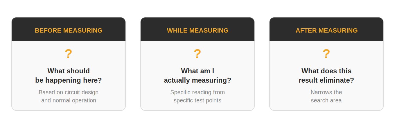
The Three Questions
Before interpreting any measurement, run through three questions:
- What should be happening here? — Based on what you know about the circuit’s design and normal operation. This forces you to understand the system before you test it.
- What am I actually measuring? — The specific reading from the specific test points. Be precise: hot-to-neutral at the load terminals of a GFCI with the device reset, not “at the receptacle.”
- What does this result eliminate? — Every valid test should either confirm a theory or rule one out. If a result doesn’t change your understanding of the problem, the test was either redundant or it wasn’t interpreted correctly.
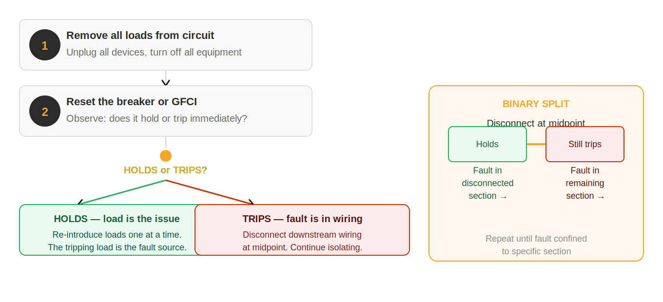
One Variable at a Time
When you change something — reconnect a wire, reset a breaker, replace a device — test the result before changing anything else. Changing multiple things simultaneously makes it impossible to know which change produced the observed effect. If you disconnect three sections of wiring at once and the problem disappears, you now need to reconnect them one at a time to find the culprit. You have not saved any time — you have created additional work.
Test Under Load
Many faults only reveal themselves when current is flowing. A high-resistance connection may read 118V at no load and 85V with a lamp connected. An intermittent backstab failure may make and break its connection when a motor starts drawing full load current. A weak breaker may hold under light load and trip when the circuit is fully loaded.
Whenever a fault is intermittent or symptoms suggest a high-resistance connection, always include a loaded measurement in your test sequence. Carry a simple plug-in load — a lamp or small heater — specifically for this purpose.
Document As You Go
Even informal mental notes — “power at outlet 1, no power at outlet 2, power at the junction box midpoint” — create a clear picture of your known-good and known-bad boundaries. Without documentation, it is easy to forget what has been tested, retest things that were already confirmed, or lose track of which half of the circuit you are currently working in.
On complex jobs, a simple diagram with test results marked at each point is worth far more than the time it takes to draw it.
When the Problem Doesn’t Make Sense
When a result is unexpected or seems to contradict what you have already found, the first response should be to recheck the test — not to explain away the result. Common sources of unexpected readings include meter leads in the wrong ports, incorrect meter mode selection, ghost voltage on de-energized conductors, and open neutrals creating misleading voltage references. Verify the test before accepting a confusing result as valid data.
A test result that doesn’t change your approach was either redundant or wasn’t understood. Every valid measurement should either confirm a theory, eliminate a possibility, or identify a new boundary. If you don’t know why you are taking a measurement before you take it, stop — figure out what question you are trying to answer first.
Common Misconceptions
These misconceptions are responsible for a significant portion of misdiagnosed faults and wasted time in the field. They are persistent because they feel logical — until you understand the physics that makes them wrong.
“Voltage equals functionality”
This is the most consequential misconception in electrical troubleshooting. A meter reading of 120V at a receptacle or device tells you that a voltage potential exists between the two measurement points. It says nothing about whether the circuit can deliver current to operate a load.
Two common scenarios where this misconception causes misdiagnosis:
- Open neutral. When the neutral conductor is broken, the hot conductor still has a voltage reference to ground through the load’s ground connection. A meter between hot and ground reads approximately 120V. But there is no complete circuit for current to flow through the load. The meter reads voltage; the load is dead.
- High-resistance connection. A badly corroded splice may pass 120V at no load because the meter draws nearly zero current. Connect a load and the voltage collapses because the connection cannot sustain current flow. Without a loaded test, this fault is invisible.
Always verify circuits under load when a fault is suspected. A lamp or plug-in heater is a more reliable circuit test than a meter reading alone.
“The most obvious component is most likely to fail”
When a receptacle is dead, the natural instinct is to replace the receptacle. When a light doesn’t work, the instinct is to change the bulb. These instincts are wrong more often than they are right.
Connection failures — backstabbed receptacles losing their spring contact, wire nuts coming loose, improperly torqued terminal screws vibrating free — are responsible for the large majority of residential electrical faults. The device itself rarely fails first. The connection between the device and the circuit is almost always the problem.
This misconception leads to a pattern of part replacement without diagnosis — changing outlets, switches, and fixtures until the problem eventually goes away, often because the act of replacing a device involved re-terminating the connections. The connection was the issue the entire time.
“Newer installations are less likely to have faults”
Age matters less than installation quality. A brand-new circuit with a backstabbed receptacle, an improperly torqued terminal, or a wire nut that wasn’t fully tightened can fail immediately under load or within weeks. Conversely, a well-installed 40-year-old circuit with properly torqued connections and no backstabbing can perform reliably for decades.
New construction and recent remodels introduce their own failure patterns: staples driven through cables, junction boxes buried without access, circuits that were energized before final inspection found code issues. Never assume that “new” means “correctly installed.”
“If the breaker didn’t trip, there’s no fault”
Standard circuit breakers are overcurrent protection devices. They respond to sustained current exceeding their rating — typically 15A or 20A in residential circuits. They do not respond to ground faults below that level, arc faults, high-resistance connections, or open neutrals. A circuit with a persistent 4mA ground fault through a person will never trip a standard breaker. An arc fault developing inside a wall cavity may never draw enough steady current to trip a breaker — but it can still start a fire.
GFCI and AFCI devices exist specifically because standard breakers leave these fault conditions undetected. If a GFCI or AFCI is tripping and a standard breaker is not, the protection device is working correctly — something is wrong with the circuit that the standard breaker cannot see.
“Intermittent problems are impossible to diagnose reliably”
Intermittent faults feel frustrating because they can’t always be reproduced on demand. But they are not random — they occur when specific conditions are met. The key is identifying the triggering condition: load-related, temperature-related, movement-related, or time-related. Once the trigger is identified, the fault can be reliably reproduced and located.
Most intermittent residential faults are connection failures that make and break based on thermal expansion, vibration, or load-induced mechanical stress. These are findable with systematic testing under load and physical manipulation of wiring at suspected locations.
Every one of these misconceptions leads to the same outcome: replacing parts or moving on to a different section of the circuit without actually finding the fault. The antidote to all of them is the same — verify with a loaded test before drawing any conclusion, and test connections before replacing devices.
Field Discipline and Process
Technical knowledge without field discipline produces inconsistent results. Technicians who follow a structured process reliably locate faults. Technicians who skip steps — even experienced ones — regularly spend more time on a job than necessary because they miss something early that they have to backtrack to find later.
Follow the Process, Not the Instinct
Experienced electricians develop strong pattern recognition. When a symptom looks familiar, the instinct is to go directly to the most common cause and fix it. This works often enough to feel like the right approach — but it fails silently in the cases where the pattern is wrong. A circuit that “looks like a bad backstab” may actually have a failing breaker. A problem that “seems like a GFCI trip” may have a different root cause.
Following the diagnostic process doesn’t slow down experienced technicians — it gives their instincts a structure to work within. If you suspect a backstab, you can still go there first, but you should verify the source and confirm the circuit scope before you do. The process takes 60 extra seconds and prevents the hour-long backtrack when the instinct is wrong.
Never Skip Verification
The most commonly skipped step is verification — confirming that the reported problem actually exists and defining exactly what it is before beginning diagnosis. This feels redundant: the customer said the circuit is dead, so it’s dead. But:
- Customers frequently misidentify the scope of the problem. “Nothing works” often means one outlet is dead.
- The problem may have resolved itself by the time you arrive. A tripped GFCI that was reset, a breaker that reset on its own.
- The symptom may be different from the description in ways that point to a completely different fault type.
Spending three minutes on verification before starting diagnosis eliminates the most common cause of wasted time: spending an hour diagnosing the wrong problem.
Change One Thing at a Time
When troubleshooting, every action you take should be a controlled test. If you disconnect three wires at once to see if a problem clears, you now have three possible causes — not one. If you replace a device and a splice and reset a breaker before testing, you don’t know which action fixed the problem. And if it didn’t fix it, you don’t know which things you can rule out.
The discipline of changing one thing, testing, recording the result, and then changing the next thing is what separates structured diagnosis from trial-and-error. It takes the same number of actions — sometimes fewer — and produces definitive results rather than guesses.
Document Boundaries, Not Just Results
The most useful information in electrical troubleshooting is boundaries — the last known good point and the first known bad point. Write these down or note them mentally as you go. When you know the fault is between outlet 3 and outlet 4, you have a defined search area. When you have a list of test results without a clear boundary defined, you may need to re-test some things you already confirmed.
Even on quick jobs, noting “good at panel, good at first outlet, dead at second outlet” takes ten seconds and creates a clear target for the next step.
Recognize When to Stop and Re-Evaluate
If you have been on the same fault for a significant time without finding it, stop and re-evaluate rather than continuing to test the same section of circuit. Common reasons a fault doesn’t surface with testing include: testing the wrong circuit, a fault condition that only appears under specific load conditions you haven’t reproduced, multiple fault points that are masking each other, or a fault in the source rather than the path.
Step back, re-read what you know, and ask whether your known-good and known-bad boundaries are actually confirmed or assumed. A single unverified assumption can send a diagnosis in the wrong direction for an entire job.