The Role of Control
Control devices determine when and how power flows from the path to the load. A system with a perfect source, an intact path, and a fully functional load will produce zero output if any control device is in a non-passing state. This makes control failures one of the most common sources of “mystery problems” — the circuit appears dead despite having power, and the diagnosis points toward wiring that is in fact completely intact.
The Frequency of Control-Related Service Calls
In residential electrical service work, a significant fraction of calls that present as “circuit failure” turn out to be control conditions not met — a switch in the wrong position, a GFCI tripped, a smart device offline, an occupancy sensor that timed out. These are not faults in the electrical sense. They are the system behaving correctly but with a condition that the customer did not recognize or know how to resolve.
The control logic check — spending 60 seconds verifying that all enabling conditions are satisfied before beginning any other diagnosis — eliminates this entire category of extended service calls. It is the highest-return investment of time in the diagnostic process: low cost, high frequency of payoff.
Control Failure vs. Control Condition
It is important to distinguish between two different situations that produce the same symptom (circuit appears dead):
- Control condition not met. The device is functioning correctly, but the enabling condition is not satisfied. The switch is off. The GFCI is tripped. The sensor has timed out. The smart device is waiting for a command. Resolution: restore the enabling condition. This is not a repair — it is a user education opportunity.
- Control device failure. The enabling condition is met, but the device is not passing power as it should. The switch’s contacts have worn. The GFCI won’t reset due to an internal failure. The timer motor has seized. The smart switch has failed. Resolution: replace the device.
The control logic check separates these two cases before any tools are needed. If the enabling condition is not met, you found the issue in 60 seconds. If the enabling condition is met and power is not passing, you have confirmed a device fault and can proceed to the LINE/LOAD test.
The 60-Second Control Logic Check
Before opening any box or taking any electrical measurement, do this check in sequence:
- Identify every switch controlling any device on the affected circuit. Confirm each is in the ON position or the completing position for multi-way systems.
- Check every GFCI in the area — the bathroom, the kitchen, the garage, outdoor locations. Press RESET on any that appear tripped. Confirm it latches. If it immediately pops back out, a fault condition is present and the GFCI is responding correctly.
- For smart or automatic controls: check the device status through its own interface (app, hub, button). Confirm the device is powered, connected, and in the ON state.
- Look for any switched outlets. In rooms without overhead lighting, one or both outlet positions may be switch-controlled. Verify the associated switch is on.
This entire sequence takes 60 seconds on a typical residential circuit. When it reveals the problem, the job is done. When it rules out control conditions, every subsequent step is more focused because control has been eliminated as a variable.
Types of Control Devices
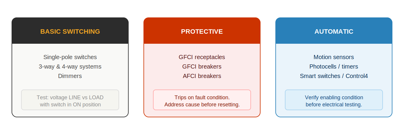
Control devices determine when and how power is delivered to loads. Understanding the three categories and their specific enabling conditions is essential before any electrical testing — a circuit that appears dead may be working exactly as designed, with a control device correctly blocking power because its enabling condition is not met.
Category 1 — Basic Switching
Basic switching devices include single-pole switches, three-way and four-way switch systems, and dimmers. Their enabling condition is mechanical: the switch must be in the position that completes the circuit.
- Single-pole switch: One switch, one enabling condition — handle ON completes the circuit. The most common missed control condition: a switched receptacle in a room without overhead lighting. The customer doesn’t know the switch exists; the “dead outlet” is working correctly.
- Three-way switch system: Two switches, and the circuit completes only when both are in the configuration that aligns the travelers. Either switch can interrupt power. A light that works from one switch but not the other has a three-way switch problem — either a failed switch or a wiring error at the common and traveler terminals.
- Four-way system: Three or more switch locations. Any one of them can interrupt power. With a four-way system, testing the circuit requires cycling every switch through its positions to confirm which combination creates the fault.
- Dimmers: Require minimum load to operate correctly. Most LED dimmers have a minimum load specification — below it, the dimmer may flicker, buzz, or not turn on at all. Also check compatibility: not all dimmers work with all LED bulb types.
Category 2 — Protective Devices
Protective devices include GFCI receptacles, GFCI breakers, and AFCI breakers. Their enabling condition is protective: they pass power only when no fault condition is present.
- GFCI receptacle: Must be in the reset state. Check by pressing the RESET button and confirming it latches. If it pops back out immediately, a ground fault condition still exists downstream — the device is working correctly and the fault must be located before reset is possible.
- GFCI breaker: Same as GFCI receptacle, but integral to the circuit breaker. Has a test button and a pigtail neutral that must be connected to the neutral bus bar. A GFCI breaker that trips with the pigtail disconnected has an internal fault — replace it.
- AFCI breaker: Trips on arc fault patterns. Will not hold reset if an arc condition is still present. Never replace an AFCI with a standard breaker to stop nuisance tripping — the arc condition must be found and corrected.
Category 3 — Automatic and Smart Controls
Automatic controls include occupancy sensors, photocells, timers, and programmable or smart switches. Their enabling conditions are environmental or programmatic.
- Occupancy sensor: Requires motion within the detection zone within the timeout period. Sensitivity, detection angle, and timeout duration are all configurable. Before electrical testing, verify these settings and confirm the sensor is powered and functional by triggering it intentionally.
- Photocell: Passes power only when ambient light is below the threshold. Testing during daylight hours will always show a non-passing state — this is correct operation, not a fault. Test after dark, or cover the sensor to simulate nighttime conditions.
- Smart switch / smart panel: Requires power to the switch, connection to the hub or cloud service, and a valid command from the control system. After a power outage, smart devices may lose programming or lose pairing with the hub. Verify device status through the app or hub interface before concluding there is an electrical fault.
Understanding Control Logic
Every control device operates based on a specific enabling condition — a state that must be present for power to pass through the device. Understanding what that condition is for each device type is essential before testing. Attempting to diagnose a circuit with an unsatisfied enabling condition produces the same readings as a device failure, and leads to unnecessary device replacement.
Enabling Conditions by Device Type
| Device | Enabling condition | Most commonly missed |
|---|---|---|
| Single-pole switch | Handle in ON position | Switched receptacle — customer doesn’t know the switch exists |
| Three-way switch system | Both switches in completing configuration | One switch left in non-completing position; circuit appears dead regardless of the other switch’s state |
| GFCI receptacle | Device reset; no ground fault present | GFCI in another room protecting the affected outlet — customer unaware of the relationship |
| AFCI breaker | No arc fault pattern; device reset | Arc condition still present — breaker trips immediately on reset; fault must be found |
| Occupancy sensor | Motion detected within timeout; sensitivity and power correct | Timeout too short; sensitivity set too low for room size; sensor in wrong mode (single-occupancy vs. multi) |
| Photocell | Ambient light below trigger threshold | Tested during daylight — condition for activation will never be met until dark. Cover sensor or test at night. |
| Timer switch | Current time within ON schedule | Timer schedule not programmed, clock wrong after power outage, or ON window doesn’t cover the test time |
| Smart switch / smart panel | Device powered, connected to hub, receiving valid ON command | Hub offline, device unpaired after power event, programming lost, or app command not reaching device |
Testing the Enabling Condition Independently
For automatic and smart controls, the enabling condition must be verified through the device’s own interface before electrical testing. A photocell circuit that reads dead electrically is correctly operating if the ambient light is above threshold — no amount of electrical testing will reveal a “fault” because there is none. An occupancy sensor that isn’t passing power may be functioning exactly as designed — the enabling condition (motion) may simply not have been met recently enough.
For smart devices: check the app or hub dashboard before touching the wiring. The device may show “offline” (a connectivity problem, not an electrical one) or “off by schedule” (a programming issue, not an electrical one). These conditions look identical to electrical faults from the wiring side but have completely different solutions.
Enabling Condition vs. Electrical Fault — The Quick Test
If you can satisfy the enabling condition manually and the circuit passes power, the enabling condition was the issue. If you satisfy the enabling condition and the circuit still does not pass power, the device has an electrical fault — proceed to the LINE/LOAD test. This distinction takes 30 seconds and determines the entire direction of the rest of the diagnosis.
Testing Control Devices
The standard test for any control device is to measure voltage on both the input (LINE) side and the output (LOAD) side, with the device in its enabled state. The comparison between these two readings tells you whether the device is passing power as it should.
The LINE/LOAD Test
- Verify the enabling condition is met. The switch is ON, the GFCI is reset, the sensor is triggered, the smart device is commanded on. If the enabling condition is not met, the device is working correctly — restore the enabling condition first.
- Measure voltage at the LINE terminals. This is the input side — the side that receives power from the upstream circuit. Should read approximately 120V hot-to-neutral when the circuit is energized.
- Measure voltage at the LOAD terminals. This is the output side — the side that delivers power to the downstream circuit or device. Should read approximately 120V when the device is in its enabled state.
- Interpret the result:
- LINE present, LOAD present → device is passing power correctly. The fault is downstream of this device.
- LINE present, LOAD absent → device is not passing power despite the enabling condition being met. The device is defective or the enabling condition is actually not satisfied.
- LINE absent, LOAD absent → no power reaching the device. The fault is upstream of this device.
Identifying LINE vs. LOAD Terminals
On GFCI receptacles, LINE and LOAD are labeled on the back of the device. LINE receives power from the upstream source; LOAD passes power to protected downstream devices. On most switches, the LINE (incoming hot) and LOAD (outgoing switched hot) may not be explicitly labeled but can be identified by the wiring configuration.
On AFCI and GFCI breakers, the LINE terminals are the bus bar connection (fixed) and the LOAD terminal is the wire lug where the circuit conductor connects.
Smart Controls and Sensors
For smart switches, occupancy sensors, and similar automatic controls, verify the enabling condition through the device’s own interface before performing electrical tests. A smart switch that shows “off” in its app is working correctly — the circuit is not supposed to have power. Verify the device status, command it to ON, and then test if the electrical output follows the command.
Interpreting LINE/LOAD Results
The four possible outcomes and their meaning:
- LINE present, LOAD present: Device is passing power correctly. If the downstream circuit is still dead, the fault is downstream of this control device — continue path or load diagnosis from this point forward.
- LINE present, LOAD absent (device in enabled state): Device is not passing power despite the enabling condition being met. The device has failed. Before replacing: double-check that the enabling condition is truly satisfied (GFCI is reset, switch is fully in ON position, sensor is triggered). If confirmed, replace the device.
- LINE absent, LOAD absent: No power reaching the device. The fault is upstream of this control device. Continue binary search upstream from this device.
- LINE present, LOAD intermittent: Device has an intermittent internal fault or the enabling condition is intermittently not being met. For mechanical switches: internal contact wear. For GFCIs: internal fault or a downstream leakage that is at the threshold. For smart controls: programming instability or connectivity issues. Monitor under load and reproduce the fault condition before concluding on device failure vs. enabling condition.
Safety When Testing GFCIs and AFCIs
GFCI and AFCI devices interrupt circuits that present shock and fire hazards. Testing these devices involves working on circuits that may have active fault conditions. Several practices reduce risk:
- When testing downstream of a GFCI or AFCI that is tripping, treat all downstream conductors as potentially energized until they have been specifically confirmed de-energized with a meter.
- Do not hold wiring while resetting a GFCI or AFCI — if the reset causes an arc at the fault location, you do not want to be touching wiring at that moment.
- When disconnecting downstream wiring for isolation testing, de-energize the circuit at the panel first, disconnect the wiring, then re-energize at the panel to test whether the protective device holds.
- If a GFCI or AFCI trips with enough force to push the handle out abruptly, there may be a significant fault condition downstream. Proceed cautiously with isolation.
GFCI and AFCI Devices
GFCI and AFCI devices are the two most commonly encountered protective control devices in residential electrical work. Both trip in response to specific fault conditions, and both require a different diagnostic approach than standard control devices.
GFCI Devices — Ground Fault Protection
A GFCI detects imbalance between the current on the hot conductor and the current returning on the neutral. Under normal conditions these are equal — all current that leaves through the hot returns through the neutral. When some current takes a different path (through a person, through moisture, through damaged insulation to ground), the imbalance exceeds 5mA and the GFCI trips.
| Condition | Diagnostic approach |
|---|---|
| GFCI trips immediately on reset | Fault condition still present. Unplug all loads. Disconnect downstream wiring at LOAD terminals. Reset. If it holds: fault is in wiring or connected loads. If it still trips: fault is in the GFCI itself or between the panel and GFCI. |
| GFCI trips only when specific device plugged in | That device is the leakage source. Test device on non-GFCI circuit to confirm. Replace or repair device. |
| GFCI trips with multiple devices, none individually | Cumulative leakage — each device is within threshold but combined they exceed 5mA. Identify highest-leakage devices by testing combinations. Consider a GFCI with a higher trip threshold for this application. |
| GFCI won’t reset, no downstream fault found | GFCI device has failed. Replace it. GFCI devices have a service life of approximately 10–15 years. |
| GFCI TEST button doesn’t trip the device | GFCI has failed in a non-protective state — power passes but protection is gone. Replace immediately. |
AFCI Devices — Arc Fault Protection
An AFCI detects the characteristic waveform pattern of electrical arcing — the irregular, high-frequency current signature produced when current jumps across a gap in damaged insulation or at a loose connection. Unlike a standard breaker, the AFCI responds to the pattern of the current, not just its magnitude.
| Condition | Diagnostic approach |
|---|---|
| AFCI trips immediately on reset | Arc condition still present. Disconnect all loads. Disconnect downstream wiring at the breaker. Reset. If it holds: arc is in the wiring or connected device. If it still trips: AFCI is defective or arc is between panel and first junction. |
| AFCI trips only when specific device operates | That device is generating an arc signature — damaged cord, failing motor, or arcing internal switch. Remove device and test on non-AFCI circuit to confirm. |
| AFCI trips intermittently with no obvious trigger | Intermittent arc in wiring — typically a staple through a cable, a pinch point, or a connection that arcs under specific vibration or thermal conditions. Isolate by disconnecting wiring sections one at a time. |
The most important rule for both GFCI and AFCI diagnosis: never replace the protective device with a standard device to eliminate the tripping. The device is doing its job. Something is wrong with the circuit. Find it.
Common Control Failures
These control-related failures account for a significant fraction of residential electrical service calls. Each one has a pattern that, once recognized, is quickly resolved.
| Failure / Condition | Symptoms | Diagnosis and Fix |
|---|---|---|
| Mechanical switch failure (contacts worn or corroded) | Load receives no power when switch is in ON position. Handle moves normally. | Measure voltage at LINE — present. Measure at LOAD — absent. Switch contacts have failed. Replace switch. |
| GFCI nuisance tripping | GFCI trips repeatedly without obvious fault. Often occurs with older appliances or motors that have high leakage current. | Test loads one at a time. Identify the device causing the trip. If the device has high leakage current and no actual fault, consider a GFCI with higher trip threshold or relocating the device to a non-GFCI circuit if code permits. |
| GFCI device failure | GFCI won’t reset, or GFCI no longer trips when tested. GFCI devices have a service life of approximately 10–15 years. | If the device won’t reset and no downstream fault is present: replace the GFCI. If the TEST button doesn’t trip the device: replace the GFCI — it has failed safe (open) rather than in the protected state. |
| Three-way switch miswiring | Circuit works in some switch combinations but not others. Often introduced during fixture replacement or switch replacement. | Map the switch travelers. Verify the common terminal connections at both switches. A common connected to a traveler — or two traveler terminals swapped — causes exactly this symptom. |
| Smart device programming loss | Smart switch or outlet stops responding after a power event. All other circuits normal. | Verify the device is powered (LED indicator or app connection). Attempt to control via app. Re-pair if necessary. Some smart devices factory-reset after extended power loss. |
| Bypassing AFCI or GFCI protection | Technician replaces AFCI or GFCI with standard device to stop tripping. Protection eliminated; fault still present. | Never bypass protection devices. This is a code violation and a safety hazard. The device was tripping because a real fault condition exists — find and fix the fault, then reinstall the protection device. |
A two-second check of every switch position and GFCI reset state before beginning any other diagnosis eliminates a large fraction of control-related service calls before any boxes are opened. Make it automatic — it costs nothing when the circuit has a genuine wiring fault, and it solves the problem immediately when a control condition is the issue.
Smart Home System Failures — A Growing Category
As smart switches, smart panels, and home automation systems become more common in residential installations, control-related service calls increasingly involve systems that have no physical malfunction — the electrical connections are perfect, but the control logic is broken due to software, connectivity, or programming issues.
Common smart home diagnostic scenarios:
- Device offline after power event. Many smart devices lose their pairing or revert to factory settings after an extended power outage or voltage fluctuation. The device is powered and the connections are intact, but it is not responding to commands. Diagnose through the app: check device connection status, attempt re-pairing, and verify hub status before any electrical testing.
- Scene or schedule not running. A circuit that should turn on at a scheduled time is not doing so because the schedule was lost or the hub is operating incorrectly. The electrical system is functioning — the control system programming is not. Verify the schedule in the app and test with a manual command before concluding an electrical fault.
- Dimmer incompatibility with LED bulbs. Many dimmers sold before the widespread adoption of LED lighting are not compatible with current-generation LED bulbs. Symptoms: flickering, humming, lights that won’t turn fully off, or lights that won’t turn on below a certain brightness level. The solution is a dimmer rated for LED loads, not a circuit repair.
- Interference between smart devices on same circuit. Some smart switches and smart devices send signals through the electrical wiring that can interfere with each other. This is a relatively rare but genuine failure mode that produces intermittent and confusing symptoms.
For smart home systems, the diagnostic principle is the same as for any control device: verify the enabling condition first (the device is powered, connected, and commanded on) before doing any electrical testing. The electrical system is almost always working correctly — the smart system is the variable.