The Purpose of Definition
Before you test anything, you must understand how the system is supposed to work. The Define step builds a clear picture of the circuit — what it contains, how power flows through it, what conditions must be met for normal operation, and where the most probable failure points are. Without this foundation, every measurement is just a number with no reference point.
The Diagnostic Value of Definition
Definition transforms testing from data collection into diagnostic reasoning. When you know what should be at a test point, every result has one of two meanings: it matches expectation (move on) or it doesn’t (investigate further). Without definition, a reading of 62V might be alarming, normal, or irrelevant — and you have no way to know which.
This is especially important for technicians still developing their intuition. An experienced technician may have built a mental library of what “normal” looks like on hundreds of circuits. A developing technician who has not yet built that library can compensate entirely by being rigorous about definition — establishing what should be present before testing, so every result is immediately interpretable.
The Four Questions to Answer Before Testing
- Where does power come from? Which breaker, what voltage, is it AFCI or GFCI type, what amperage?
- How does it reach the load? Through which rooms, in what sequence, through which devices?
- What is supposed to be operating? Every outlet, fixture, and device served by this circuit.
- What must be true for it to operate? Every control condition — switch positions, GFCI reset status, sensor states, smart device programming.
With these four answers in place, you can state a specific expectation before every test, and every result either confirms what you know or tells you something new. This is the operational definition of diagnostic efficiency.
When to Spend More Time on Definition
Simple familiar circuits need only seconds. Complex or unfamiliar circuits — three-way switching, MWBCs, circuits with smart controls, post-remodel wiring — warrant deliberate mapping before testing. As a rule: if you are uncertain what a measurement result means, stop and improve your definition before continuing. The uncertainty is not in the measurement — it is in your model of the circuit.
Mapping the Circuit
Circuit mapping is the process of tracing the physical and logical path of a circuit before opening any boxes. For simple circuits a mental map takes seconds. For complex circuits that have been modified over time — added outlets, extended runs, remodeled spaces — mapping deliberately before testing prevents wasted effort opening boxes that are outside the fault area.
What to Establish Before the First Test
- The source: Which breaker, what amperage, what type (standard, AFCI, GFCI).
- The path order: What sequence do devices appear in? Which outlet feeds the next one? Where does the circuit branch, if at all?
- Every load on the circuit: All outlets, fixtures, and hardwired devices — not just the ones reporting problems.
- Every control device: Every switch, GFCI, sensor, timer, and smart device in the path.
Series (Daisy-Chain) vs. Parallel Branch Topology
Most residential outlet circuits are wired in series — power enters the first device and passes through to the next in sequence. A fault at any device interrupts power to all devices downstream of it. This topology means the boundary between working and non-working devices directly identifies the fault location: it is at the last working device or in the connection between it and the first dead device.
Some circuits branch — power reaches a junction and splits into multiple sub-runs. In a branched circuit, a fault on one branch does not affect the other. When you find that some devices on a circuit are dead while others on the same circuit work, and the dead ones are not simply downstream of the working ones in a daisy chain, the circuit may have a branch configuration. The junction point (usually a junction box) is the starting point for diagnosis of that branch.
Reading the Physical Layout
The physical layout of the building gives you significant information about the circuit’s likely path even before you open any boxes. Outlets on the same wall frequently share a circuit run. Rooms adjacent to each other often share circuits. Kitchen and bathroom circuits run through walls from the panel to their first device and then daisy-chain along the room. Knowing the likely physical path helps you choose good binary search midpoints — accessible boxes that are roughly halfway between the confirmed good point and the confirmed bad point in the circuit’s actual routing, not just in room count.
Updating Your Map as You Test
The initial map is a hypothesis. As you test, you refine it. An unexpected test result — voltage absent where you expected it to be present, or present where you expected it to be absent — is information about the actual circuit configuration. The map should update with each test. By the time you have located the fault, your map of the circuit should be significantly more accurate than when you started — and that accuracy is useful for future service calls on the same system.
Identifying the Power Flow
Understanding how current flows through a circuit — and what prevents it from flowing — is the physical foundation of every measurement you take. Every diagnostic technique in this course is ultimately an application of circuit theory. Getting this right prevents the most common class of misdiagnosis: concluding a circuit is functional based on a voltage reading that does not account for current path.
The Complete Circuit Requirement
Current flows only through a complete circuit — a continuous conducting path from the source, through the load, and back to the source. Every conductor in that path must be intact and capable of carrying the required current. Breaking any part of the path — a broken conductor, an open connection, an open neutral — stops current flow completely, regardless of what the voltage at any single point appears to be.
This is the most important single concept in electrical diagnosis. Voltage can exist across an open circuit. Current cannot flow through one. A meter measures voltage — it does not confirm that current is flowing or that a complete circuit exists.
Hot, Neutral, and Ground — Their Roles
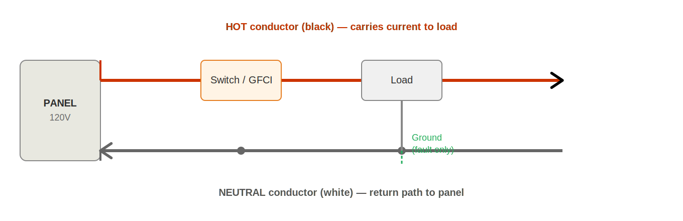
The hot conductor carries current from the panel to the load at line voltage (~120V relative to neutral and ground). The hot is the energized conductor — it is what a breaker interrupts when it trips, and what your meter detects when it reads voltage.
The neutral conductor carries current from the load back to the panel at near-zero voltage under normal conditions. The neutral is as essential as the hot — without a complete neutral return path, no current can flow through the load. An open neutral produces misleading voltage readings that do not reflect circuit function.
The ground conductor does not carry current under normal operation. It provides a low-impedance path for fault current — if a hot conductor contacts a grounded metal part, current flows through the ground to the panel, tripping the breaker or GFCI. The ground does not contribute to normal circuit operation, but its presence is critical for safety and for GFCI function.
What Happens at Each Element
At the source (breaker): full line voltage appears between hot and neutral. The breaker limits maximum current. At each connection in the path: a small voltage drop occurs proportional to the connection’s resistance and the current flowing through it. A good connection drops less than 0.5V. A high-resistance connection may drop 5–50V — enough to significantly affect load operation. At the load: the remaining voltage drives current through the device to do work. At the neutral return: current flows back to the panel at approximately 0V relative to ground.
Understanding this voltage progression tells you what to expect at every test point. Any deviation from expectation is a diagnostic finding: a higher-than-expected drop indicates resistance, an absence of voltage indicates an open, an unexpected voltage presence indicates a fault path.
Testing Both Directions
Always measure both hot-to-neutral and hot-to-ground at every test point. Hot-to-neutral tests the complete delivery circuit including the neutral return. Hot-to-ground tests the hot conductor’s relationship to the grounding system. When these two readings diverge significantly — normal hot-to-ground but low or zero hot-to-neutral — the neutral is open between this point and the panel. This two-reading comparison is the single most reliable method for detecting open neutral conditions.
Understanding Control Logic
Control devices are the most commonly overlooked category in electrical diagnosis. A system with a perfect source, a complete path, and a functional load will produce zero output if a control device is blocking power — and the symptom looks identical to a path fault.
The Enabling Condition Concept
Every control device has an enabling condition — a specific state that must be present for power to pass through it. Before diagnosing any suspected path or load fault, confirm that all enabling conditions are currently satisfied:
- Single-pole switch: Handle must be in the ON position.
- Three-way switch system: Both switches must be in the configuration that completes the circuit. Either switch can interrupt power depending on the current state of both.
- Four-way switch system: All switches must be correctly positioned. With a four-way system, three or more switch locations control the same fixture — any one of them can interrupt power.
- GFCI receptacle or breaker: Device must be reset. No ground fault condition can be present at the moment of reset — if a fault still exists, it will trip again immediately.
- AFCI breaker: No arc fault pattern can be present. If the arc source still exists, the breaker will trip as soon as it is reset.
- Occupancy sensor: Motion must have been detected within the programmed timeout period. The sensor must be powered and configured correctly. Day/night sensitivity settings must match current conditions.
- Photocell: Light level must be below the trigger threshold. A photocell controlling outdoor lighting will not pass power during daylight hours.
- Timer: Current time must be within the programmed ON schedule.
- Smart switch or smart panel: Device must be powered, connected to its hub or cloud service, and receiving a valid command. Programming must not have been lost due to a power event.
The Control Logic Check
Before testing any circuit for a path or load fault, spend 60 seconds on the control logic check:
- Identify every control device in the circuit — every switch, every GFCI, every sensor or timer.
- Confirm each one is in its enabled state.
- Check every GFCI on the circuit and in adjacent locations for a tripped state.
- If smart controls are present, check their status independently (app, hub, or direct control at the device).
This check takes under two minutes and eliminates an entire category of diagnosis when it reveals the problem. A circuit that was never enabled by a control device is not a wiring fault — it is a control condition that was not met.
Establishing Expected Conditions
Before measuring, state what you expect to find. This single habit is the difference between reactive testing and diagnostic testing. If you measure without an expectation, you cannot know whether the result is normal or a clue. If you state your expectation first, every result is immediately meaningful.
Expected Values Reference
| Test point | Expected | If different — suspect |
|---|---|---|
| 120V outlet, hot-to-neutral | 114–126V | Open neutral, open hot, upstream fault |
| 120V outlet, hot-to-ground | 114–126V | Open ground, or open hot |
| Neutral-to-ground at outlet | 0–2V | If >5V: open neutral upstream or neutral-ground fault downstream |
| Switch in ON, line-to-load | 0V (passes through) | If ~120V: switch contacts failed — not closing |
| Switch in OFF, line side | ~120V | If 0V: no power reaching the switch — upstream fault |
| GFCI LINE terminals | ~120V hot-to-neutral | 0V: no upstream power — check breaker |
| GFCI LOAD terminals (reset) | ~120V hot-to-neutral | 0V with LINE present: GFCI tripped or defective |
| 240V circuit, L1-to-L2 | 228–252V | ~120V: one leg lost. ~0V: both legs same phase or both lost |
| Outlet under load (lamp) | Within 5V of no-load | >5V drop: high-resistance connection upstream |
Applying the Expectation Habit
Before every measurement, complete this sentence: “I expect to find _____ because _____.” The “because” is the important part — it forces you to connect the expected value to your understanding of the circuit. If you can’t complete the “because,” your circuit model is incomplete and more definition work is needed before testing.
When a result doesn’t match your expectation, that discrepancy is the diagnostic finding — not the number itself. A reading of 62V hot-to-neutral is meaningless without context. The same reading compared to an expectation of 120V tells you immediately that either the hot is partially lost, the neutral is partially open, or there is a high-resistance connection somewhere upstream.
Identifying Possible Failure Points
Once you understand the circuit, you can identify the most probable failure locations before opening a single box. This turns testing from a search into a targeted investigation — you know where to look first because experience and statistics tell you where faults actually occur.
Failure Probability by Location
Residential path failures are not randomly distributed. They concentrate at specific locations due to specific mechanisms. Testing in order of probability means you will find the fault faster on average across all the jobs you do.
Highest probability: Backstabbed receptacles and switches. The spring-contact back-stab terminals on residential devices are the most common single source of path faults in occupied homes. Their spring contacts fatigue under load cycling, reducing contact area and increasing resistance progressively until the connection fails. The failure often shows up at the most heavily loaded device on the circuit — typically the first device downstream from the panel — because that device carries the full circuit current.
High probability: Wire nut splices. Wire nuts applied with insufficient twist, with strands incompletely captured, or without proper size matching for the conductor count and gauge will loosen over time. Thermal cycling is the primary mechanism — the conductors expand when loaded and contract when cooled, progressively working a marginal connection loose. Wire nuts in attics and crawl spaces face the most extreme thermal cycling and fail at disproportionately high rates.
Moderate probability: Device terminal screws. Connections made by feel rather than torque specification loosen over years of thermal cycling and vibration. Aluminum conductors require special attention — aluminum expands and contracts at a different rate than the steel or brass terminals, and without anti-oxidant compound and proper torque, aluminum terminations develop high resistance rapidly.
Lower probability but high consequence: Panel connections. Bus bar connections and breaker clips loosen through the same thermal cycling mechanism as downstream connections. These are lower probability because the panel environment is more stable and less subject to vibration, but when they fail they can be difficult to distinguish from downstream path faults without testing at the panel specifically.
The First-Device Rule
In a daisy-chain circuit, the first device downstream from the panel carries the full circuit current — all current passes through its terminals before distributing to subsequent devices. This makes the first-device connections the highest thermal-stress point in the circuit and therefore disproportionately likely to be the fault location when an intermittent or high-resistance problem exists. When a circuit fault is not immediately obvious, checking the first device is almost always the second step (after confirming the source).
Using Probability in Practice
You do not need to follow probability order rigidly — the binary search method is still faster than any sequential approach. But probability reasoning tells you which boxes to open when you have arrived at the fault section and are choosing where to inspect first. Between a wire nut splice and a backstabbed device in the same fault section, inspect the backstabbed device first. The probability that it is the fault source is higher, the inspection is faster, and the repair (re-terminating on a screw) eliminates the failure mechanism entirely.
Recognizing System Variations
Real-world residential circuits frequently deviate from the textbook single-circuit diagram. Understanding common system variations prevents misdiagnosis and ensures accurate testing.
Multi-Wire Branch Circuits (MWBCs)
An MWBC uses two hot conductors from opposite legs of the panel sharing a single neutral. When correctly configured, the currents on the two hots partially cancel on the shared neutral, allowing the neutral to carry less current than either hot individually. MWBCs are common in kitchens, where they allow two 20A circuits to share a single conduit run.
MWBC identification and testing:
- In the panel, look for two breakers that are tied together (handle tie or two-pole breaker) sharing a single white neutral conductor.
- Both breakers must be on opposite legs — measure L1-to-L2 voltage; it should read approximately 240V. If it reads 0V or approximately 0V, both legs are on the same phase — a dangerous configuration that overloads the neutral.
- An open shared neutral on an MWBC is particularly dangerous: both circuits’ loads become connected in series across 240V. Devices rated for 120V may see far more than their rated voltage.
Switched Receptacles
Many living rooms and bedrooms have switched receptacles — one or both outlets on a receptacle controlled by a wall switch. This is the standard installation for rooms without overhead lighting. The switched outlet powers a floor or table lamp controlled at the wall.
A switched receptacle that doesn’t work is not a wiring fault — it is the switch in the OFF position, or the hot tab broken on the receptacle to split its outlets. Always check for a wall switch before diagnosing a dead receptacle in a living area without overhead lighting.
Feed-Through Wiring at Devices
In daisy-chain circuit configurations, power enters a device at its terminal connections and exits on additional wires routed to the next device in the chain. The device itself is a point in the path, not just a load at the end. A failed connection at this device — particularly a backstabbed one — interrupts power to every device downstream of it.
When you find a dead section of circuit, the fault location is often at the last working device — at the connection where power should pass through to the next device, but isn’t. This is why “the device before the dead section” is always one of the first places to inspect.
Remodels and Undocumented Junctions
Older homes and those with remodel history frequently have junction boxes buried in walls, ceilings, or attics that are not reflected in any documentation. These junctions contain splices that may have been made hastily during renovation work and are not accessible for inspection without opening walls.
When a fault cannot be found at any accessible point, consider whether an undocumented junction may exist between the last working point and the first dead point. The binary search method will still locate the fault area, but you may need to open a wall section to access the junction.
Shared Neutrals at Older Panels
In some older installations, separate circuits share a neutral that was not identified as an MWBC at installation — an unintentional MWBC created by a previous electrician taking a shortcut. These can be particularly dangerous because they are not on a double-pole or tied breaker. If you find a neutral that appears to serve more than one circuit, investigate carefully before working on either circuit.
Working in Homes with Aluminum Branch Circuit Wiring
Aluminum branch circuit wiring was used extensively in residential construction from approximately 1965 to 1973. It is identifiable by the silver color of the conductor (versus the orange-copper color of copper wire) and often by conductor markings that include “AL” or “ALUMINUM.” Aluminum wiring itself is electrically sound, but its coefficient of thermal expansion differs from that of the copper and steel alloys used in device terminals. Over years of load cycling, this differential expansion works aluminum conductors loose from standard terminals, creating high-resistance connections that generate heat.
When working on aluminum-wired circuits, every connection point is a higher-probability fault location than it would be in a copper-wired circuit. Use only devices rated “CO/ALR” for aluminum wiring connections — these have the correct terminal geometry and alloy to accommodate aluminum conductors properly. Apply anti-oxidant compound to all aluminum terminations. Never use CO/ALR-rated wire nuts or push-in connectors that are not specifically listed for aluminum.
Signs that aluminum wiring requires attention: warm outlet covers, outlets that are slightly discolored, lights that flicker under load, or circuits that have had repeated connection failures. A circuit with these signs may warrant re-terminating every connection point with proper CO/ALR materials as a preventive measure.
Knob-and-Tube and Early Wiring Systems
In homes built before approximately 1940, knob-and-tube wiring may still be present — individual conductors (not sheathed cables) supported by ceramic knobs and threaded through ceramic tubes at framing penetrations. Knob-and-tube is ungrounded and has no neutral bundled with the hot — the conductors run separately. This makes circuit tracing and fault isolation more complex because you cannot find a “cable run” — the hot and neutral may be physically separated throughout their run.
When working in homes with knob-and-tube wiring, additional caution is warranted: the insulation is rubber-based and may be brittle after decades of service. Handle conductors gently — insulation that appears intact from the outside may crack and expose the conductor when flexed. Do not add loads to circuits that already show signs of insulation degradation without full replacement of the affected section.
Sub-Panels and Detached Structure Circuits
Garages, workshops, and detached structures often have their own sub-panel fed from the main house panel. A dead circuit in a detached structure may indicate a fault in the sub-panel feed, the sub-panel itself, or the branch circuit — all of which require testing at different points along the supply chain. Apply the source verification sequence to the sub-panel before investigating branch circuits: confirm that the feeder conductors are delivering voltage to the sub-panel bus, then confirm individual breaker outputs as needed.
For sub-panels in detached structures, also verify that the neutral and ground are properly separated at the sub-panel (not bonded, as they are at the main panel) and that the grounding electrode system for the detached structure is intact. A sub-panel with bonded neutral and ground will cause nuisance GFCI trips and other diagnostic confusion.