Open Neutral Diagnostics
An open neutral is one of the most commonly misdiagnosed faults in residential electrical work. The reason is counterintuitive: when the neutral is broken, a meter can still read approximately 120V at the affected device. This voltage reading leads technicians to conclude the circuit is functional and the device must be defective — a conclusion that is wrong.
Why Voltage Appears with an Open Neutral
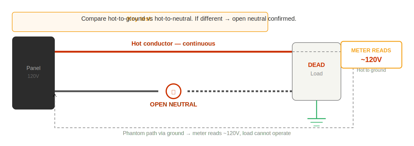
When the neutral conductor is broken, the hot conductor is still connected and at 120V relative to ground. The device at the end of the circuit has a ground conductor that is bonded to the neutral at the panel. A meter measuring between hot and ground at the device reads approximately 120V — because the hot is at 120V and the ground is at 0V, and the measurement is valid. But there is no complete circuit. Current enters the device on the hot, reaches the open neutral, and stops. No current flows. The device is dead.
The meter reads voltage not because the circuit is functional, but because the meter is measuring a potential between two reference points — neither of which requires a complete circuit to establish a voltage difference.
The Diagnostic Test
Compare hot-to-neutral with hot-to-ground at the test point:
- Working circuit: Hot-to-neutral ≈ 120V, hot-to-ground ≈ 120V. Both readings approximately equal.
- Open neutral: Hot-to-neutral ≈ 0V (or very low), hot-to-ground ≈ 120V. Significant discrepancy between the two readings.
This two-reading comparison is the diagnostic signature of an open neutral. It is definitive and takes under 30 seconds.
Locating the Open
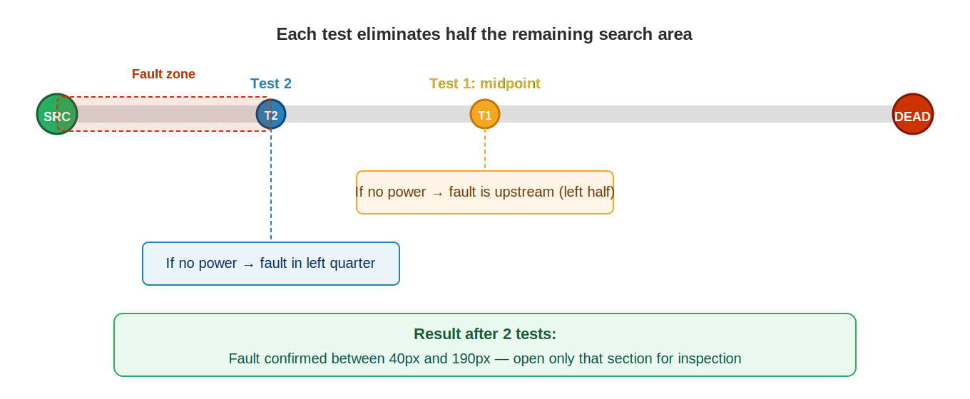
Once an open neutral is confirmed at the device, apply the binary search method to the neutral conductor path. Move upstream from the dead device toward the panel, testing hot-to-neutral at each accessible point. The transition from low to normal hot-to-neutral reading identifies the boundary — the open neutral is between the last point with a low reading and the first point with a normal reading.
Most common locations for open neutral faults:
- Backstabbed neutral at the last working device in the chain — the spring contact has failed on the neutral conductor specifically
- Loose wire nut on the neutral splice in a junction box
- Neutral conductor that worked free from a terminal screw — often due to thermal cycling or undertorqued installation
- Broken neutral conductor inside a cable, typically at a point where the cable has been repeatedly flexed or was stapled too tightly
Open Neutral on MWBCs — Especially Dangerous
On a multi-wire branch circuit, an open shared neutral is particularly dangerous. The two hot conductors from opposite legs are still energized. With the neutral open, the two 120V loads become connected in series across 240V. Each load now sees a voltage determined by its resistance relative to the total — devices with lower resistance see higher voltage, potentially far above their 120V rating. This can immediately destroy connected equipment and is a fire hazard. Any circuit with a suspected open neutral should be de-energized at the panel until the neutral is repaired.
Always compare hot-to-neutral with hot-to-ground when voltage is present but nothing works. A discrepancy between these two readings is the diagnostic signature of an open neutral — one of the most common faults in residential electrical and one of the most commonly missed.
AFCI Tripping
AFCI (arc fault circuit interrupter) devices detect patterns of electrical arcing and interrupt power before arcing can ignite surrounding materials. Arc faults are a leading cause of residential electrical fires. AFCI protection is required by the NEC in bedrooms, living areas, and most habitable spaces in new construction.
What Arc Faults Look Like
An arc fault is not a hard short circuit — it is current jumping across a gap. The gap may be in damaged insulation, at a loose connection, or through a nail or staple that has penetrated a cable. The current during arcing is irregular and high-frequency rather than steady, which is why a standard breaker — which responds only to sustained overcurrent — cannot detect it. The AFCI processes the waveform of the current in real time and recognizes the characteristic signature of arcing.
Arc faults are often intermittent. They may occur only under specific load conditions, only when a particular device is operating, only when the circuit is warm, or only during vibration. This intermittency makes them challenging to locate — the AFCI may trip unpredictably from the user’s perspective, and the fault may not be present when you first test the circuit.
Diagnostic Sequence
- Confirm the trip. Was this a genuine AFCI trip (indicated by the TEST button being in the tripped position) or just a standard overcurrent trip? Some AFCI breakers also provide overcurrent protection and can trip for either reason.
- Remove all loads. Unplug every device from every outlet on the circuit. Turn off hardwired loads.
- Reset and observe. If it trips with no loads: the arc source is in the wiring. If it holds: the arc source is in a connected device — proceed to load isolation.
- Reintroduce loads one at a time. If load isolation: add one device at a time, operate it for 30–60 seconds. When the AFCI trips, the last device added is the arc source. Common causes: damaged power cords, failing motors with worn brushes, arcing internal switches in appliances.
- Binary search the wiring. If the arc is in the wiring: disconnect wiring at the midpoint, reset, observe. Holds: arc is in disconnected section. Trips: arc is in remaining connected section. Continue until isolated to a specific section. Then physically inspect: look for staples through cables, pinch points, damaged insulation at corners, or any point where the cable was subjected to mechanical stress during installation or subsequent work.
Common Arc Fault Sources in Residential Wiring
- Staples driven through cables. Over-driven staples can pierce the insulation and create a direct conductor-to-conductor path, or create an intermittent path that arcs under load. Most common in older construction where staple guns were used without attention to depth.
- Cables pinched at corners. Cables running through tight corners or around framing can have insulation abraded at the contact point, eventually creating arcing under vibration or load.
- Loose connections at devices. A loose terminal connection that is not tight enough to create a permanent open circuit but not tight enough to prevent arcing under current.
- Damaged cords on appliances. Vacuum cleaner cords, extension cords, and appliance cords that are repeatedly kinked, pinched, or run under furniture develop internal damage that creates arcing under load.
GFCI Tripping
GFCI (ground fault circuit interrupter) devices trip when they detect an imbalance between the current flowing out on the hot conductor and the current returning on the neutral. Under normal conditions, these currents are equal — all current that leaves through the hot returns through the neutral. When some current takes an alternate path to ground (through a person, through water, through damaged insulation), the imbalance exceeds the 5mA trip threshold and the GFCI interrupts power.
Understanding What GFCIs Detect
The GFCI is not detecting a high current — it is detecting a current imbalance. This is why a 5mA ground fault trips a GFCI but would never trip a 15A or 20A circuit breaker. The breaker responds to total current; the GFCI responds to the difference between hot and neutral current. This makes GFCIs effective at detecting leakage paths that a standard breaker cannot see.
Implications for troubleshooting:
- The GFCI can trip even when no device is plugged in — if the wiring itself has a leakage path to ground.
- The GFCI can trip due to cumulative leakage from multiple devices, none of which individually exceeds the trip threshold.
- The GFCI trip threshold (5mA) is well below the current that causes physical sensation (~1mA) and far below the current that causes ventricular fibrillation (~100mA).
Diagnostic Sequence
- Disconnect all loads. Unplug every device from all outlets protected by this GFCI (including downstream outlets not on the same physical device). Turn off any hardwired loads on the circuit.
- Reset the GFCI. If it holds with no loads: the problem is in a connected device — proceed to step 3. If it trips with no loads: the problem is in the wiring — proceed to step 4.
- Reintroduce loads one at a time. Plug in one device, wait 30 seconds, observe. If the GFCI holds, add another. Continue until the GFCI trips — the last device added is the cause. Test that device on a non-GFCI circuit to confirm it is the leakage source.
- Isolate the wiring. If the GFCI trips with no loads connected, disconnect the downstream wiring at the LOAD terminals of the GFCI (or at a midpoint in the downstream wiring). Reset. If it now holds: fault is in the disconnected downstream section. If it still trips: fault is in the wiring between the panel and the GFCI itself.
Common Causes and Their Signatures
- Moisture intrusion. Outdoor receptacles, bathroom or kitchen fixtures, areas near water. Often intermittent — trips when wet, holds when dry. Inspect for water in boxes, damaged weatherproof covers, or condensation inside conduit.
- Damaged cords or appliances. A specific device always causes the trip. The leakage path is within the device — worn insulation, moisture in the motor, or a faulty power supply. Replace or repair the device.
- Neutral-to-ground contact downstream. If the neutral and ground conductors touch anywhere downstream of the GFCI, the GFCI detects a current imbalance even with no load. Any current returning through the neutral also has a path back through the ground, creating the imbalance. Look for misidentified conductors, improperly terminated neutrals, or neutral-ground connections that should not exist downstream of the GFCI.
- Cumulative leakage. Each appliance on a GFCI circuit has some natural leakage current — typically well below 1mA individually. If many devices are connected, their combined leakage can exceed 5mA. This is sometimes seen in circuits with many electronic devices, older appliances, or long cable runs. Test devices individually to identify which combination exceeds the threshold.
GFCIs detect current imbalance, not just faults. Even small leakage currents — individually acceptable from each device — can collectively exceed the trip threshold when many devices share one GFCI circuit. Always test loads one at a time rather than assuming the wiring is at fault because the GFCI trips with “everything plugged in.”
Intermittent Faults
Intermittent faults are the most challenging to diagnose because they cannot always be reproduced on demand and may pass all standard tests. But they are not random — they occur when specific conditions are met, and those conditions can be identified and reproduced with the right approach.
The Nature of Intermittent Faults
Almost all residential intermittent faults are connection failures — a connection point that makes and breaks depending on specific conditions:
- Load-triggered. The connection is marginal and fails when current demand exceeds a threshold. Works fine under light load (lamp), fails under heavier load (vacuum cleaner, heater). Caused by backstabbed connections, undertorqued terminals, or fatigued spring contacts.
- Temperature-triggered. The connection is adequate when cold but fails when the conductor or terminal expands under thermal load. Or fails when cold (overnight, winter) because the conductor contracts enough to create a gap. Thermal faults are among the most difficult because they may not be reproducible during a daytime service call.
- Mechanical / vibration-triggered. The connection fails when the circuit is physically disturbed — a door slamming, a washing machine’s spin cycle vibrating the wall, someone walking near the junction box. These connections are almost loose enough to fail at all times and need very little additional disturbance.
Diagnostic Techniques
Load testing. Always the first step. Connect a representative load and monitor voltage continuously. Many intermittent connections fail within seconds of full load current being applied. Watch for voltage drop, flicker, or collapse.
Wiggle test. While monitoring voltage at a test point downstream of the suspected fault area, physically flex and manipulate conductors at each connection point — push on the device, flex the cable where it enters the box, push wire nuts in and out. A change in the meter reading during manipulation identifies the fault location definitively.
Thermal testing. If the fault is temperature-related, it may require recreating the thermal condition. For high-temperature faults (connection fails when hot): run the circuit under full load for 15–30 minutes, then test. For low-temperature faults: this may require testing in the early morning when ambient temperatures are lowest.
Inspect regardless. Even if you cannot trigger the fault directly, systematically inspect every high-probability connection in the fault area: backstabbed devices, wire nuts, terminal screws. A connection that looks marginal — discolored, with insufficient strand engagement, barely snug when the device is tugged — should be corrected even without definitively reproducing the fault. You are almost certainly finding and fixing the intermittent connection.
Documentation
For intermittent faults that cannot be definitively reproduced and confirmed during the service call, document carefully:
- What connections were inspected and corrected.
- What the previous condition was (backstabbed, loose wire nut, etc.).
- What was done (re-terminated on screw, replaced wire nut, torqued to spec).
- That the repair was made as a preventive correction of marginal connections, and that the customer should call back if the symptom returns.
This documentation protects you professionally and gives the customer clear information about what was done and what to expect.
Multi-Wire Branch Circuit (MWBC) Issues
A multi-wire branch circuit (MWBC) uses two hot conductors from opposite legs of the panel sharing a single neutral conductor. When installed correctly, the shared neutral carries only the difference between the two circuits’ currents — not the sum — allowing it to be sized the same as either hot conductor despite serving two circuits.
How a Correct MWBC Works
In a 120/240V residential panel, the two bus bars are energized from opposite phases of the utility transformer — they are 180 degrees out of phase with each other. When two circuits are connected to opposite legs, their return currents on the shared neutral are out of phase and partially cancel. If both circuits are carrying 10A, the neutral carries 0A. If one carries 10A and the other carries 5A, the neutral carries 5A. The neutral is always at or below the maximum load of either circuit — which is why the NEC permits a single neutral to serve both circuits.
For this cancellation to work, the two hot conductors must be on opposite legs — one connected to each bus bar. This requires a two-pole breaker or two single-pole breakers with a handle tie in the panel.
What Happens with Same-Leg Wiring
If both hot conductors are connected to the same bus bar — the same leg — the return currents on the neutral are in phase and add rather than cancel. Two circuits each carrying 10A produce 20A on the neutral. The neutral, sized for a single circuit’s load, is now carrying twice its rated current. This generates heat proportional to the square of the current — four times more heat than a correctly wired MWBC at the same load level. The neutral conductor overheats, which can damage insulation, cause fire, or ultimately produce an open neutral fault.
Same-leg MWBC wiring is a code violation, a fire hazard, and a common source of confusing diagnostic findings because everything may appear normal under light load and fail progressively as loads increase.
Identifying and Testing MWBCs
- At the panel: look for two breakers with a handle tie or a two-pole breaker sharing a single neutral conductor. The neutral should be bonded to both circuits’ hots at the source — not to just one.
- Verify phasing: measure hot-to-hot voltage between the two circuit conductors at the panel. Should read approximately 240V if on opposite legs. If it reads approximately 0V, both circuits are on the same leg — the MWBC is miswired.
- Load test: clamp the neutral conductor and measure current with both circuits loaded at a representative level. On a correctly phased MWBC the reading should be well below the sum of the two circuits’ currents. On a same-leg MWBC it will equal or exceed that sum.
Open Neutral on an MWBC
An open shared neutral on an MWBC is one of the most dangerous fault conditions in residential wiring. With the neutral open, the two circuits become series-connected across 240V. Each circuit’s loads now see a voltage determined by the ratio of their resistance to the total circuit resistance — which changes dynamically as devices switch on and off. Devices may be exposed to voltages well above 120V. This immediately destroys sensitive electronics and is a fire risk. Any suspected open shared neutral on an MWBC should result in de-energizing both circuits at the panel immediately.
Whenever working on a circuit that shares a neutral with another circuit, confirm the phasing before doing anything else. A same-leg MWBC overloads the neutral silently — no breaker will trip, no obvious symptom will appear until the neutral overheats enough to cause visible damage or failure. The 30-second hot-to-hot voltage test at the panel is the only reliable way to confirm correct phasing.
Voltage Present but Nothing Works
The scenario of normal voltage readings at a dead receptacle or device is one of the most instructive and frequently mishandled situations in field troubleshooting. The meter says the circuit is working. The load says it isn’t. One of them is providing more information than the other — and it is the load.
Why the Meter Can Lie
A standard multimeter draws approximately 1–5 microamps during a voltage measurement. This is not a load — it is a negligible current. The voltage the meter reads is the potential that exists when virtually no current flows. For a circuit with an open neutral or a severely degraded splice, this no-current potential can appear perfectly normal while the circuit is completely unable to operate even a 5W LED lamp.
The two root causes:
- Open neutral. Current enters the load on the hot, but cannot return through the broken neutral. The voltage reference to ground via the load’s ground connection gives the meter a reading. No current flows through the load.
- High-resistance connection. The splice or terminal can pass the microamps the meter draws at essentially no voltage drop. Apply even modest current — a lamp, a phone charger — and the voltage drops significantly or collapses entirely.
The Diagnostic Protocol
- Do not trust the no-load voltage reading. Note it, but do not conclude the circuit is functional based on it alone.
- Connect a real load. A lamp is ideal — simple, visible, and draws enough current to expose high-resistance connections. Observe whether the lamp lights. Measure voltage across the load while it is connected.
- Compare hot-to-neutral and hot-to-ground. In a working circuit, both readings are approximately equal (~120V). With an open neutral, hot-to-ground reads approximately normal but hot-to-neutral reads zero or near zero. With a high-resistance connection, both readings may appear reduced under load.
- Apply the binary search to the neutral. Once an open neutral is confirmed, trace the neutral path using the binary search method. Find the last point where hot-to-neutral reads normal. The open is between that point and the next junction downstream.
Most Likely Locations
- Backstabbed neutral at the last working receptacle in the chain — the connection that should pass the neutral to the next device has failed.
- Wire nut splice in a junction box — the neutral wire nut has loosened or was never fully engaged.
- Neutral terminal at a GFCI or switch — the neutral conductor was not fully seated and came loose.
Voltage without current delivery is meaningless for load operation. Always verify the circuit can deliver power by connecting a real load and observing the result. The difference between a no-load voltage test and a loaded test is the difference between finding the fault and missing it entirely.
Panel and Breaker Failures
Panel and breaker failures produce symptoms that are indistinguishable from downstream wiring faults until you check source output voltage directly. If source verification is skipped, these faults consume significant time as the technician searches for a path fault that does not exist.
Breaker Failure Modes
Breakers fail in several distinct ways, each producing different symptoms:
- Internal trip (hidden). The breaker trips internally after an overcurrent event but the handle does not fully move to the obvious middle position. The handle appears ON; output voltage is absent. This is the most common missed breaker failure.
- Contact degradation. Repeated cycling and thermal stress wear the internal contact surfaces. The breaker makes intermittent contact — output voltage is present at no load but collapses under load, or flickers during motor starting.
- Mechanical failure. The internal mechanism fails such that the handle moves freely but the contacts do not actually open or close with it. Handle position is meaningless.
- Thermal element degradation. The breaker’s internal bimetal element loses calibration over time. The breaker trips at lower than rated current — nuisance tripping under normal loads — or fails to trip at rated current.
Bus Connection Failures
The breaker’s connection to the panel bus bar can fail independently of the breaker itself:
- The spring-clip or bolt connection to the bus bar loosens through thermal cycling.
- Corrosion builds up on the bus bar connection surface, increasing resistance.
- The bus bar itself develops a connection problem at the main lug or at a point serving multiple breakers.
Bus connection failures typically produce voltage that is present at no load but drops significantly under load — the resistance of the connection creates a voltage drop proportional to current. A bus connection fault looks like a high-resistance path fault until you test at the breaker output terminal specifically and compare to the bus voltage.
Diagnostic Sequence
- Confirm the correct breaker using physical verification — not just the panel label.
- Visually inspect the breaker: handle position, discoloration, signs of heat.
- Measure voltage at the breaker output terminal (hot-to-neutral, hot-to-ground).
- If output is absent or reduced: measure voltage at the bus bar itself.
- Compare: if bus has voltage and breaker output does not, replace the breaker. If bus voltage is also absent or reduced, the problem is upstream.
- For intermittent problems: test under load. Apply the circuit’s rated load and measure output voltage while loaded.
Panel Replacement Considerations
When multiple breakers in a panel are exhibiting problems, or when the bus bar itself has heat damage, the issue may be systemic rather than isolated to a single breaker. Signs that a panel replacement evaluation is warranted:
- Multiple breakers failing in a short period.
- Bus bar discoloration or evidence of previous arcing.
- Panel age (some panel manufacturers had defective production runs that are now well-documented).
- Evidence of overheating in the main lug area.
Panel evaluation and replacement is beyond the scope of routine troubleshooting but should be communicated to the customer when observed conditions suggest it.
A failed breaker produces exactly the same downstream symptoms as a wiring fault — nothing works on that circuit — until you measure voltage at the breaker output terminal. That one test takes ten seconds and can save an hour of unnecessary path tracing. Never skip source verification.