The Role of the Load
The load is the component that consumes electrical energy to perform work — a receptacle, fixture, appliance, motor, or any device served by the circuit. The Load step answers one question: is this specific device capable of operating when supplied with correct power?
Loads are frequently blamed for circuit faults because they are the most accessible part of the system and the most visible point of failure. The instinct to replace a dead outlet or a non-working fixture is understandable — it is faster than diagnosis. But replacing the device without confirming the circuit can deliver power to it means that the real fault remains, and the new device will eventually fail for the same reason.
Load Testing as a Differential Test
The purpose of load testing is not to confirm that a device is working — it is to separate the device from the circuit as a variable. Once you know definitively whether the device or the circuit is the problem, you can act with confidence: replace the device, or continue with circuit diagnosis. Without this separation, any action you take is a guess.
The definitive load test is substitution: replace the suspect device with a known-good device of similar type. If the substitute works, the original device is defective. If the substitute also fails, the circuit is the problem. This is the most direct possible test and should be the first option whenever substitution is practical.
When Substitution Is Not Practical
For hardwired fixtures, built-in appliances, or equipment that cannot be quickly swapped, use the loaded voltage test instead: connect a plug-in load (a lamp, a resistive heater) at the circuit’s test point and measure voltage while the load is operating. Compare to the no-load reading. A drop of more than 5V confirms a high-resistance connection in the path. A stable reading at approximately source voltage confirms the circuit can deliver power — if the original device still doesn’t work, it is defective.
The Pattern to Avoid
The most common load-related diagnostic error is replacing a device, having it work, and concluding the original device was defective — without verifying that the act of replacing it also involved re-terminating connections. Many “device failures” are actually connection failures that were resolved incidentally when the device was replaced and the wiring was reconnected. The new device will exhibit the same “failure” when the new connection degrades. Always test the circuit with the new device under load before closing up, and inspect the connections that were disturbed during replacement.
Voltage vs. Usable Power
The most consequential misunderstanding in electrical troubleshooting is equating the presence of voltage with the availability of usable power. A meter reading of 120V at a device does not mean the circuit can operate that device. This misunderstanding is responsible for more unnecessary device replacements and misdirected diagnostic work than any other single conceptual error.
What a Voltage Measurement Actually Tells You
A multimeter measuring voltage between two points detects a potential difference — a voltage exists between those points. It does not tell you how much current can flow through that potential. The meter itself draws negligible current during a voltage measurement — typically in the range of 1–5 microamps on a standard digital multimeter. This is far too little current to reveal that a connection cannot sustain milliamps, let alone the amps required to operate real loads.
The distinction: voltage is a property of the circuit at a point in time. Current delivery is a function of the complete circuit under load. These are different things, and a meter reading confirms only the first.
Scenario 1 — Open Neutral
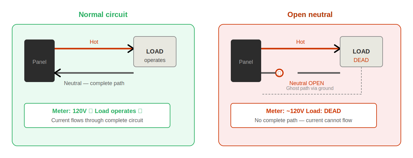
When the neutral conductor is broken, the hot conductor is still present at 120V relative to the grounding system. The connected device has a ground conductor bonded to the neutral at the panel. A meter measuring hot-to-ground reads approximately 120V — because the hot is at 120V and the ground is at 0V, and neither fact requires a complete circuit to be true.
But there is no complete circuit. Current from the source can reach the device on the hot conductor and accumulate — but it has nowhere to go. There is no neutral return path. The device is completely dead. The meter reads 120V. These two facts seem contradictory until the physics is understood: voltage can exist without current flow, and a meter reading does not confirm current flow.
The diagnostic signature: hot-to-neutral reads near zero or zero. Hot-to-ground reads approximately 120V. This discrepancy is the open neutral confirmation test.
Scenario 2 — High-Resistance Connection
A severely degraded splice or a fatigued backstab spring connection may pass the tiny current drawn by a meter — producing a reading that appears normal — but cannot sustain the higher current drawn by a real load. Connect a 60W lamp and the voltage drops. Connect a 1,500W heater and the voltage may collapse to near zero. The connection is “there” in the sense that it makes contact, but it is not capable of delivering power.
The physics: the connection has resistance. V = IR. At 5 microamps, even 10,000 ohms produces only 0.05V drop — invisible. At 10 amps, 10 ohms produces 100V drop — catastrophic. Real high-resistance connections are typically in the 1–50 ohm range, enough to produce 10–500V drop at load current. The meter reading tells you nothing about this because the meter doesn’t draw enough current to produce a measurable drop.
The Loaded Test — Always the Answer
Whenever voltage is present but a load fails to operate, the next test is always a loaded test:
- Connect a known-good resistive load (a lamp is ideal) to the circuit at the test point.
- Measure voltage at the load terminals while the load is energized and operating.
- Compare to the no-load reading.
If voltage holds stable within 3–5V of the no-load reading and the lamp lights normally: the circuit can deliver power, the original device is likely defective.
If voltage drops significantly or the lamp is dim: high-resistance connection upstream. The circuit cannot deliver adequate power. The original device may also be defective, but the circuit must be repaired first.
If voltage holds at approximately 120V but the lamp doesn’t light: open neutral (confirm with hot-to-neutral vs hot-to-ground comparison).
Verifying Load Operation
Three methods for verifying whether a load is the source of a problem. Use the most appropriate method for the situation. Substitution is almost always the fastest and most definitive.
Method 1 — Test the Device on a Known-Good Circuit
Take the suspect device to a circuit you have confirmed is working — another outlet in a different room, or a circuit that has been tested and is known good. Connect the device and observe operation.
- Device works on known-good circuit → device is good. The problem is in the installed circuit. Return to source and path diagnosis.
- Device fails on known-good circuit → device is defective. Also test the installed circuit with a known-good device to confirm the circuit is functional.
Best for: plug-in devices. Limitations: not suitable for hardwired equipment. Time: 2–3 minutes.
Method 2 — Substitute a Known-Good Load
Connect a known-good device to the installed circuit at the fault location. A plug-in lamp is ideal — simple, inexpensive, and draws enough current to expose marginal connections.
- Substitute works → original device is defective, circuit is functional.
- Substitute fails → circuit cannot deliver power. The original device may also be defective, but the circuit must be diagnosed and repaired first.
- Substitute works at first then fails under extended operation → intermittent high-resistance connection in the circuit path.
This is the most commonly useful method. A plug-in lamp in your bag costs almost nothing and produces a definitive result in 10 seconds. Use it on every suspected load fault before any other approach.
Method 3 — Loaded Voltage Measurement
When substitution is impractical, connect a representative load and measure voltage at the device terminals while the load is operating:
- Connect a resistive load drawing current similar to the original device’s rating.
- Measure hot-to-neutral and hot-to-ground at the device terminals under load.
- Stable reading within 5V of source voltage → circuit can deliver power, device is likely defective.
- Voltage drops significantly under load → high-resistance connection upstream. Circuit cannot deliver adequate power.
- Hot-to-neutral near zero, hot-to-ground near 120V → open neutral. No complete circuit exists regardless of device condition.
Best for: hardwired equipment, motors, HVAC. Also useful as a final verification after repair — confirm the circuit delivers stable voltage under real load conditions before considering the job complete.
Choosing the Right Method
If you can physically swap the device: use Method 1 or 2. If you cannot: use Method 3. If you have any doubt about whether voltage is stable under load: use Method 3 regardless of which other method you also used. A loaded voltage measurement takes 30 seconds and confirms circuit quality in a way that no-load testing cannot.
Testing Under Load
Testing under load is the diagnostic step that reveals what voltage testing alone cannot: whether the circuit can deliver current, and whether any connection in the path is marginal enough to fail under real-world demand.
The Physics of High-Resistance Connections
A high-resistance connection is invisible to a standard no-load voltage test because the meter draws negligible current — typically less than 5 microamps. Ohm’s law: V = IR. At 5 microamps, even a 10,000-ohm resistance produces only 0.05V of drop — undetectable. At 10 amps (a circuit running a vacuum cleaner), the same 10,000-ohm resistance would produce 100,000V of drop — impossible, meaning the voltage would collapse entirely rather than reach the load.
Real residential high-resistance connections are typically in the range of 1–100 ohms, not 10,000. But even a 5-ohm connection on a 10-amp circuit produces 50V of drop — reducing a 120V supply to 70V at the load, which causes motors to run hot, lights to dim, and devices to malfunction or fail entirely. This fault is completely invisible at no load and very obvious under load.
The Load Test Procedure
- Connect a load representative of what the circuit normally serves — a lamp for a lighting circuit, a heater or high-draw appliance for an outlet circuit.
- Measure hot-to-neutral at the device terminals while the load is energized and operating.
- For motor loads: take the measurement after the motor has fully started. Starting current is higher and may briefly expose connections that steady-state current would not.
- Compare to no-load voltage. Acceptable drop: 2–4V (1–3%). Concerning: 5–10V. Critical: over 10V.
- Monitor for 30–60 seconds on suspect circuits. Some intermittent connections make initially and then open as heat builds at the fault point.
Load Testing for Motor Circuits
Motors and compressors draw significantly more current at startup than during steady-state operation — often 3–6 times the running current. This inrush surge exposes marginal connections that would otherwise never be seen. When servicing circuits that serve HVAC equipment, refrigerators, pumps, or other motor loads:
- Start the equipment from a cold state while monitoring voltage — observe both the startup voltage dip and recovery.
- A large startup dip that recovers to normal: connection is marginal but holding. Monitor it and consider proactive repair.
- A startup dip that does not recover: high-resistance connection that cannot sustain motor running current. This is causing motor stress and shortened equipment life.
- Equipment that fails to start under its own load: connection may have collapsed entirely under inrush current.
Every circuit serving HVAC equipment, a refrigerator, a washing machine, or any other motor load should be tested under load as part of the confirmation step — not just when a fault is suspected. High-resistance connections that are not yet causing noticeable symptoms are already shortening equipment life and will eventually cause a service call. Finding and correcting them proactively is better service than waiting for the callback.
Differentiating Load vs. Circuit Problems
The most useful diagnostic question in load testing is: is this the device’s fault, or is this the circuit’s fault? The following observations provide definitive answers.
| Observation | Conclusion | Next action |
|---|---|---|
| Device fails on multiple different circuits | Device is defective | Replace device. Verify installed circuit works with a substitute load. |
| Multiple different devices fail on same circuit | Circuit is the problem | Return to source and path diagnosis. Loads are fine. |
| Device works on other circuits, not this one | Circuit is the problem | Diagnose the installed circuit. Device is confirmed good. |
| Voltage present, device performance poor or erratic | High-resistance connection or open neutral — not a device fault | Test under load. Compare hot-to-neutral vs hot-to-ground. Locate path fault. |
| Replacing device does not resolve problem | Fault is upstream of the device | Return to circuit diagnosis. Replacement confirmed device is not the fault location. |
| Device works intermittently at installed location only | Connection fault at device location or immediately upstream | Inspect terminals at this device and the last junction upstream. Wiggle test under load. |
| Replacing device fixes problem, but same problem returns weeks later | Connection fault that was incidentally disturbed during replacement — not actually a device fault | Inspect all connections at this location. Re-terminate on screw terminals with proper torque. Do not backstab. |
Substitution testing is the fastest path to a definitive answer. Ten seconds with a plug-in lamp tells you more than ten minutes of reasoning about whether the device might be defective. When in doubt, substitute first — then decide what to diagnose.
The Circuit vs. Device Decision Tree
When diagnosing a failed load, apply this decision sequence to reach a definitive conclusion efficiently:
- Is voltage present at the device terminals?
- No → circuit fault. Do not test the device. Diagnose the circuit first.
- Yes → proceed to step 2.
- Connect a known-good load. Does it operate?
- No → circuit cannot deliver power despite showing voltage. Test under load; compare hot-to-neutral vs hot-to-ground; diagnose the circuit.
- Yes → circuit is functional. The original device is likely defective. Proceed to step 3.
- Test the original device on a confirmed working circuit. Does it operate?
- Yes → original device is good. Something about its specific installation location is causing the fault. Return to circuit diagnosis at that location specifically.
- No → original device is defective. Replace it.
This three-step sequence eliminates the main sources of load misdiagnosis and reaches a definitive conclusion before any parts are ordered or replaced. The total time invested is typically under 5 minutes, and the result is certainty rather than educated guessing.
Understanding Load Failure Modes
When a device is confirmed defective, understanding why it failed informs the repair and prevents recurrence:
- Wear failure. The device reached end of its operational life. Switches, dimmers, and motor-driven devices have finite mechanical and electrical life cycles. A switch that has been operated thousands of times may fail with no other contributing factor. Replacement is the appropriate response, with no circuit investigation needed unless the new device also fails.
- Voltage stress failure. The device was exposed to voltage outside its rated range — either sustained overvoltage from a utility issue or a transient surge. Look for other devices on the same circuit or in the same area that also show signs of failure. If multiple devices failed at the same time, voltage stress from a utility event is likely.
- Thermal failure. The device was operated in conditions that exceeded its thermal rating — a dimmer used below its minimum load threshold running continuously, a motor device in a location with inadequate ventilation, or a device rated for intermittent use that was run continuously. The replacement must be rated for the actual application.
- Ground fault failure. Some device failures are caused by an internal ground fault — moisture intrusion, insulation breakdown, or winding failure in a motor. If a device failure caused a GFCI trip, the device developed an internal ground fault path. The device is defective, but the GFCI response was correct. Replace the device; do not bypass the GFCI.
Circuit Quality After Load Repair
After replacing a defective device, always test the circuit under load before closing up and considering the job complete. This is part of the confirmation step, but it has particular importance after load replacement because the act of replacing a device involves re-terminating connections — and the quality of those terminations determines how long the repair will last.
Before installing the replacement device:
- Inspect the conductors for adequate length — there should be sufficient wire to reach the terminals comfortably with no tension on the termination.
- Inspect for any damage to the insulation at the device location — nicks, abrasion, or discoloration suggest the conductors were mistreated during previous work.
- Re-strip the conductor ends to clean copper if any oxidation is visible.
- Do not backstab — terminate all conductors on screw terminals, torqued to specification.
After installing the replacement device, test under the load conditions that best approximate normal use. Measure voltage at the device terminals while the load is energized. Confirm the voltage is stable and within normal range. This confirms both that the new device is functional and that the circuit connections were made correctly.
Real-World Examples: Circuit vs. Device Decision
The following scenarios illustrate how the circuit vs. device decision framework applies to common field situations. Each shows the observation, the correct interpretation, and the action that follows.
Example 1 — Vacuum cleaner won’t run at one outlet, works at another.
Observation: customer’s vacuum works in the bedroom but not in the living room. Both outlets tested with a standard meter read approximately 120V. Conclusion: the meter reading does not confirm circuit functionality. The living room circuit may have an open neutral (reading via ground reference) or a high-resistance connection (reading at no load). Correct action: connect a lamp to the living room outlet. If the lamp lights: the circuit can deliver power, and the vacuum’s plug or cord should be tested. If the lamp doesn’t light or is dim: the circuit has a fault that the meter missed. Diagnose the circuit.
Example 2 — New LED fixture replaced an older fixture, doesn’t work.
Observation: an existing circuit that powered a working fixture now produces no output with a new LED fixture installed. The existing wiring was not modified. Conclusion: the circuit was working before the new fixture was installed, so the circuit is likely not at fault. The new fixture may be defective, or there may be a wiring compatibility issue with the new fixture’s driver circuit. Correct action: test the circuit with a plug-in lamp at the fixture wiring. If the lamp lights: the circuit is functional, and the new fixture or its installation is the issue. If the lamp doesn’t light: something was disturbed during installation — inspect the connections made during installation before investigating the fixture itself.
Example 3 — Range hood stopped working after kitchen remodel.
Observation: range hood was working before remodel, not working after. Other devices on same circuit also dead. Conclusion: the remodel likely disturbed a connection. The fault pattern (multiple devices dead) suggests a path fault rather than a device fault. Correct action: verify source, identify the circuit boundary (last working device, first dead device), binary search the section between them. Focus inspection on any connections that were accessible during remodel work — junction boxes that were opened, cable runs that passed through remodeled spaces.
Example 4 — Garage door opener trips GFCI.
Observation: new garage door opener is installed and trips the GFCI outlet every time it operates. The old opener never tripped it. Conclusion: the new opener has higher leakage current than the GFCI threshold permits, or it generates electrical noise that the GFCI interprets as an imbalance. This is a device-circuit compatibility issue, not a wiring fault. Correct action: test the opener on a non-GFCI outlet (where code permits) to confirm it is the leakage source. Options: use a GFCI with a higher trip threshold, use a surge-suppressor between the opener and the GFCI outlet, or consult the opener manufacturer about GFCI compatibility.