The Role of the Path
The path is the complete physical route electricity travels from the source to the load and back — every conductor, every splice, every terminal, every internal device connection. Path failures are the most common category of residential electrical fault, responsible for the large majority of service calls.
The Path’s Hidden Complexity
A residential branch circuit looks simple in a diagram: a wire from the breaker to the first outlet, then to the next, and so on. In practice, a typical 15A circuit in a 1,500-square-foot home contains:
- 50–120 feet of conductors
- 8–15 connection points at devices (2–4 terminals per device)
- 4–10 wire nut splices in junction boxes
- 2–6 devices with backstab options
- 1–3 junction points that may be undocumented
Each of these is a potential failure point. The path is not wire — it is a series of electrical junctions, each of which can degrade, loosen, corrode, or fail over years of thermal cycling, vibration, and current load.
Why Path Failures Are So Common
Connection quality degrades over time through predictable mechanisms. Thermal cycling — the expansion and contraction that occurs every time a circuit is loaded and cooled — gradually loosens connections that were not torqued to specification. Vibration from appliances, HVAC equipment, or construction works connections loose over months and years. Backstabbed connections fail as their spring contacts fatigue under load. These are not rare events — they are the normal aging process of electrical connections in a lived-in building.
The result is that in a home more than 10–15 years old, path connection quality is the primary diagnostic concern on any circuit with intermittent behavior, reduced output, or complete failure.
Path Testing Strategy
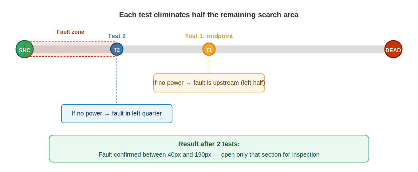
The binary search method — testing at the midpoint of the unknown section, determining which half contains the fault, and repeating — locates path faults in the minimum number of tests. The key discipline is to always test at genuinely accessible midpoints (outlets, switches, accessible junction boxes) and to record confirmed-good and confirmed-bad boundaries as they are established. The fault is always between the last confirmed-good point and the first confirmed-bad point, and never anywhere else.
The Binary Search Method
The binary search method is the most efficient approach to locating a fault in a circuit with multiple potential failure points. Rather than testing sequentially from one end to the other — which in the worst case requires testing every point — binary search divides the circuit in half with each test, guaranteeing that the fault is located in the minimum number of tests.
Why Binary Search Works
In a circuit with N potential fault locations, sequential testing requires up to N tests in the worst case. Binary search requires at most log₂(N) tests. For a circuit with 32 potential points, sequential testing could take 32 tests; binary search takes at most 5. For a circuit with 16 potential points, binary search takes at most 4 tests.
In practice, residential circuits typically have 5 to 15 accessible test points. Binary search locates the fault in 3 to 4 tests in the average case.
Step-by-Step Application
- Confirm the boundaries. Verify that the source is good (voltage present at breaker output). Verify that the failure exists (test at the dead device — no voltage or device doesn’t operate). These establish the known-good point (source) and the known-bad point (dead device).
- Identify a midpoint. Find a test point approximately halfway between the source and the dead device. This might be an outlet, a junction box, or a fixture. Choose the point that most evenly divides the circuit.
- Test at the midpoint. If voltage is present: the fault is downstream (between midpoint and dead device). If voltage is absent: the fault is upstream (between source and midpoint).
- Repeat in the half containing the fault. Choose a point midway through the half that contains the fault. Test again.
- Continue until confined. Keep halving the search area until the fault is confined between two adjacent known points. Then open and inspect only that section.
Choosing Good Midpoints
The best midpoints are accessible locations where voltage can be measured without extensive disassembly: outlets, switches, and junction boxes with accessible covers. Choose midpoints that divide the circuit as evenly as possible. In a chain of five outlets, outlet 3 is the ideal first midpoint — it divides the circuit into two halves of roughly equal length.
Recording Results
As you work through the binary search, track your known-good and known-bad points. A simple note — “good at outlet 3, bad at outlet 4” — creates a clear target and prevents you from re-testing points you have already confirmed. Without records, it is easy to lose track of what half of the circuit you are currently searching.
Mastery of binary search is one of the clearest markers of an experienced troubleshooter. A technician who works sequentially might open four boxes to find a fault between boxes 4 and 5. A technician using binary search in a 10-device circuit opens one box to learn which half contains the fault, then one more to narrow it further, then opens the specific box where the fault is. Three openings versus ten — with a guarantee of finding it.
Testing Methodology
At every path test point, take at minimum two measurements: hot-to-neutral and hot-to-ground. These two readings together reveal the fault type and confirm the neutral’s integrity in a way that neither measurement alone can provide.
Why Two Readings Are Required
Hot-to-neutral measures the complete delivery circuit — the hot going out and the neutral returning. If the neutral is open anywhere in the circuit upstream of this test point, the hot-to-neutral reading will be abnormal even if the hot conductor is perfectly intact. Hot-to-ground measures the hot conductor relative to the grounding system. Ground integrity is independent of neutral integrity, so this reading is not affected by neutral faults in the same way. The combination of these two readings together provides more information than either one alone.
The Dual-Reading Interpretation Table
| Hot-to-neutral | Hot-to-ground | Interpretation |
|---|---|---|
| ~120V | ~120V (equal) | Normal — hot and neutral both intact. Test under load to confirm no high-resistance connection. |
| 0V | 0V | No hot conductor reaching this point — open or disconnected hot upstream. This test point is the new known-bad boundary. |
| ~0V | ~120V | Classic open neutral signature. Hot present, neutral broken. Meter reads hot-to-ground via ground reference but no complete circuit. The load is dead despite this “voltage.” |
| Drops under load | Drops proportionally under load | High-resistance connection upstream. Connection cannot sustain current — voltage drops across the resistance as current increases. |
| ~120V | ~0V | Open ground. Hot and neutral intact — circuit works, but ground conductor is broken. Safety concern, not an operational fault. Should be corrected. |
| ~60V (unstable) | ~120V | Ghost voltage on the hot, with an open or disconnected hot conductor. Hot-to-ground reads phantom voltage induced from adjacent live conductors; hot-to-neutral shows the inconsistency. Use a low-impedance tester to confirm. |
Test Under Load as Standard Practice
The dual readings above are most informative when taken under load conditions that approximate the circuit’s normal use. For any circuit that:
- Has shown intermittent behavior
- Serves a motor, compressor, or high-draw device
- Has a history of problems or has a device that reported underperformance
- Shows readings that are slightly below normal without being obviously abnormal
…always include a loaded measurement. Connect a lamp or resistive load and observe both readings while the load is energized. A reading that drops 5V or more under load reveals a high-resistance connection that the no-load test showed as normal. This is the most common category of fault that no-load testing misses entirely.
Recording Test Results
As you work through a circuit, record the results at each test point — even informally, even just a mental note of “good at 3, bad at 4.” The test results build a map of confirmed-good and confirmed-bad locations. Without this map, it is easy to lose track of what the current search boundaries are and re-test points that were already confirmed. A recorded result is a permanent boundary; an unrecorded result is just a vague recollection that may or may not be reliable when you need it.
Common Path Failure Locations
While a path fault can occur anywhere, decades of field experience show that certain locations are responsible for the overwhelming majority of residential path failures. Prioritizing these locations during isolation means you will find most faults in fewer steps.
Backstabbed Receptacles — Highest Priority
Backstabbing is the practice of pushing conductors into the spring-contact holes on the back of a receptacle rather than using the terminal screws on the sides. The spring contacts provide a quick connection during installation but have a finite service life. Under load cycling, the springs fatigue, the contact area decreases, resistance increases, and eventually the connection fails entirely.
Signs of a backstabbed connection problem: intermittent or complete loss of power at one or more outlets in a chain, power that is present at no load but fails under load, outlets that are warm to the touch. Always check backstabbed connections at the first device in the non-working section of a circuit.
The fix for a backstabbed connection is always the same: remove the conductor from the back-stab hole and re-terminate it on the side screw terminal, torqued to specification. Do not simply re-insert the conductor into the backstab — the spring is already fatigued.
Wire Nut Splices
Wire nut failures occur in several ways:
- The wire nut was applied with insufficient torque and the connection loosened over time.
- Not all conductor strands were captured in the wire nut — one or more strands are making no contact.
- The wire nut is undersized for the number and gauge of conductors it is joining.
- The connection was solid initially but loosened under thermal cycling.
When inspecting a wire nut splice, pull gently on each conductor after removing the nut. A properly made splice should hold each conductor firmly. A conductor that slides out easily was not adequately captured.
First Device Downstream from Panel
The first device in the circuit carry the full circuit load — all current passes through its connections before distributing to subsequent devices. This high thermal stress makes the first-device connections disproportionately likely to fail, particularly on circuits that are frequently loaded near their rated capacity.
Improperly Torqued Terminals
NEC and device manufacturers specify torque values for terminal connections — typically 12–14 in-lb for standard outlet terminals. Connections made by feel rather than specification are frequently undertorqued, creating a marginal connection that fails progressively as it loosens under thermal and mechanical stress. A connection torqued to specification will outlast the device; an undertorqued connection may fail within years.
Junction Boxes from Previous Work
Remodels, additions, and circuit extensions frequently create junction boxes in inaccessible locations — buried in walls, above drop ceilings, in attics. These junctions were often made hastily and may contain poor-quality splices. When a fault cannot be found at any accessible point, consider whether an undocumented junction exists in the fault area.
Identifying and Correcting Each Fault Type
Backstabbed connections: To identify, pull gently on each conductor at the backstab insertion point after removing the device from the box. A properly captured conductor should not pull free. A fatigued backstab contact may release the conductor easily, or may produce a slight movement or click. Even if the conductor does not release, a backstabbed connection on a circuit that has shown any signs of high-resistance behavior should be re-terminated on screw terminals as a preventive measure — the incremental time is minutes, and the failure mechanism is permanently eliminated.
To re-terminate: use the appropriate screwdriver for the terminal type, loop the stripped conductor end clockwise around the screw so that tightening draws the conductor into the connection, and torque to the device manufacturer’s specification — typically 12–14 in-lb for standard outlet terminals. Use a torque screwdriver for this — feel-tightening is not reliable enough to meet specification, particularly for technicians who have not developed a calibrated sense for terminal torque.
Wire nut splices: Remove the wire nut and inspect the conductors. Verify that all strands of all conductors are fully inside the wire nut and twisted together. A conductor that can be pulled free from the splice without rotating the wire nut was not properly captured. Re-make the splice: strip conductors to the correct length for the wire nut size, pre-twist the conductors together with pliers before applying the wire nut, and apply the wire nut with enough rotation that the conductor tails are fully drawn into the connector. The wire nut should resist being unscrewed by hand without significant effort when properly made.
Choose wire nuts sized for the specific conductor count and gauge. A connector rated for two 14-gauge conductors will not make a reliable connection with four 12-gauge conductors. Wire nut sizing charts are printed on most connector packaging — reference them rather than estimating.
Improperly torqued terminal screws: For suspected undertorqued connections, use a torque screwdriver or a ratcheting torque tool calibrated to the correct range. Most residential device terminals specify 12–14 in-lb. On aluminum conductors or in damp locations, apply listed anti-oxidant compound before tightening. Re-torque all terminal connections in a box while it is open — it costs nothing and systematically improves every connection that was originally made by feel.
The First-Device Priority
When binary search has isolated a fault to a section of circuit, the first device in that section is almost always the highest-probability fault location. Open it first. Inspect both its internal connections (for backstabbing) and the quality of the wire nut splices in the box (if any). In the majority of residential circuit fault investigations, the fault is found at or within two devices of the first device in the isolated section.
This is not a rule that eliminates binary search — it is a prioritization within the identified fault section that tells you which box to open first once the section has been confirmed. Combine binary search (to define the section) with first-device prioritization (to identify the most likely location within the section) for maximum efficiency.
The Isolation Rule
The Isolation Rule is the foundational principle of path fault localization:
This rule is absolute and has no exceptions. Once you have confirmed power is present at one point and absent at another, the fault is definitively in the section between those two points — and nowhere else. You do not need to search outside this boundary. Every test you take either moves the good boundary forward or moves the bad boundary back, progressively confining the search area until the fault section is specific enough to inspect directly.
Boundaries Must Be Confirmed, Not Assumed
The Isolation Rule is only as useful as the accuracy of your boundaries. A boundary is established by measurement — not by assumption, not by a panel label, not by the customer’s report. “The source must be good because the breaker is on” is an assumption. “The source is confirmed good because I measured 120V stable under load at the breaker output” is a confirmed boundary.
Every incorrectly assumed boundary sends the search into the wrong section of the circuit. The most damaging version of this error: assuming the source is good and spending an hour on path testing, only to find a failed breaker. The entire hour was spent outside the actual fault area because one boundary was assumed rather than confirmed.
Moving Boundaries Efficiently
In a chain of accessible test points, the binary search method moves boundaries with maximum efficiency. Each test at a midpoint either moves the good boundary forward (if voltage is present) or moves the bad boundary back (if voltage is absent). After two tests, the search area is one quarter of the original. After three tests, it is one eighth. The fault is located in a specific section after at most log₂(N) tests.
In practice, the “midpoint” may not be perfectly centered — accessible test points are where they are. Choose the most central accessible point available, not the most convenient one. A test at outlet 4 in a 10-device circuit is more valuable than a test at outlet 2, even if outlet 2 is slightly easier to reach.
The Boundary After a Repair
After a repair, the boundary must be re-confirmed by testing — not assumed to have moved because a connection was fixed. A repair that resolves the fault will show power restored throughout the previously-bad section. A repair that did not fully address the fault will show the boundary in the same position. Test after every repair before concluding the job is complete. The boundary does not move because you made a repair — it moves when measurement confirms the fault condition has changed.
Special Conditions
Three special path conditions require techniques beyond standard voltage testing. Recognizing them prevents misdiagnosis and wasted effort.
Ghost / Phantom Voltage
Ghost voltage is induced voltage detected by a standard multimeter on a conductor that is not connected to an active source. It occurs because a de-energized conductor running in the same cable or conduit as live conductors picks up voltage through capacitive coupling — the electric field from the live conductor induces a measurable potential on the adjacent conductor.
Ghost voltage has two characteristic properties: it cannot deliver current (connecting a load makes it disappear or collapse to near zero), and it reads inconsistently — the exact value varies depending on test lead position and ambient conditions.
How to confirm and eliminate ghost voltage:
- Connect a resistive load to the circuit. Ghost voltage collapses; real source voltage remains stable.
- Use a low-impedance tester (Wiggy). Its internal load draws enough current to collapse ghost voltage, showing zero on de-energized conductors.
- The test: if your meter reads voltage on a conductor but a lamp connected to that circuit doesn’t light, you almost certainly have ghost voltage or an open neutral.
Voltage Present but Nothing Works — Open Neutral
This condition is responsible for enormous amounts of misdiagnosis. The meter reads approximately 120V at the receptacle or device. The load does not operate. The natural conclusion — that the circuit is fine and the load is defective — is wrong in the majority of these cases.
When the neutral is open, the hot conductor is still present and the load’s ground connection provides a voltage reference to ground. The meter, measuring between hot and ground, reads approximately 120V. But there is no complete circuit — no return path through the neutral — so no current can flow through the load. The voltage is real; the circuit is broken.
The diagnostic test: compare hot-to-neutral with hot-to-ground at the test point. In a working circuit, both readings are approximately equal (~120V). With an open neutral, hot-to-ground reads approximately normal, but hot-to-neutral reads zero or near zero. This discrepancy is the diagnostic signature of an open neutral.
Intermittent Faults
Intermittent path faults — connections that make and break depending on load, temperature, vibration, or time — are the most challenging to locate because they may not be present when you test. Several techniques help:
- Test under load. Most intermittent connection faults appear under current. Connect a representative load to the circuit and monitor voltage while manipulating suspect wiring.
- Wiggle test. While monitoring voltage at a test point, physically flex and manipulate conductors at each suspected connection point. A change in reading during manipulation — voltage drop, flicker, or complete loss — confirms the location of the intermittent connection.
- Temperature cycling. If the fault is temperature-related, it may not appear until the system has been running long enough to heat up. Allow the circuit to operate under load for a period before testing, or — for cold-weather faults — test after a period of non-operation in a cold space.
- Inspect high-probability locations regardless. Even without reproducing the fault, systematically inspect every backstabbed connection and every wire nut splice in the fault area. If a connection looks marginal — discolored, loose, or with insufficient strand engagement — correct it. You are likely fixing the intermittent fault even without definitively reproducing it.
Ghost voltage is one of the most common causes of misdiagnosis in path testing. A reading on a “de-energized” conductor looks like a source problem — the breaker appears to be on, there’s voltage on the conductors, but nothing works. Always confirm suspected ghost voltage with a load test or low-impedance tester before concluding the source is functional.