The Purpose of Verification
Verification is the process of confirming that a reported problem actually exists and defining exactly what it is before beginning any diagnosis. It is one of the most important and most frequently skipped steps in the troubleshooting process.
The impulse to skip it is understandable — the customer already described the problem, so why repeat it? The answer is that customer descriptions of electrical problems are almost always imprecise. They describe what they observe, not what is happening electrically. “Nothing works” usually means something is wrong, but the scope, nature, and severity are almost never accurately communicated.
Three Things Verification Produces
- Confirmation the problem exists. You have personally observed the fault behavior under the conditions that reveal it — not just heard about it secondhand.
- A precise failure category. Not “the circuit doesn’t work” but “complete loss of power at all outlets on this circuit” or “device operates for 10 seconds then cuts out under compressor load.”
- A defined scope. Which devices are affected and which are not — establishing a boundary that immediately limits the diagnostic search area.
These three outputs make every subsequent step faster. A well-verified problem is already partially diagnosed. The boundary between working and non-working devices is often the single most valuable piece of information in the entire diagnostic process.
What Skipping Verification Costs
The most common consequence of skipping verification is spending significant time diagnosing the wrong problem. Examples:
- A customer reports “no power in the kitchen.” A technician who skips verification checks the panel, tests circuits, and spends 30 minutes before discovering a tripped GFCI that would have been found immediately with a two-minute scope check.
- A customer reports “lights flickering constantly.” Without verification, the technician assumes a loose connection at the fixture. Verification reveals the flickering only occurs when the dishwasher motor starts — pointing immediately to a load-triggered high-resistance connection on a shared circuit.
- A customer reports “outlet stopped working.” Verification reveals the outlet is switch-controlled — the wall switch was in the off position. The “fault” was a design feature the customer wasn’t aware of.
Reproducing the Problem
The first task in verification is to reproduce the issue under real conditions. This means operating the system in the same way the customer normally uses it and observing its behavior directly. Until you have personally observed the fault, you are working from secondhand information.
Operating the System as the Customer Does
Ask the customer to demonstrate the problem, or operate the system yourself in exactly the way it is normally used. This matters because the triggering condition may not be obvious:
- A circuit that fails only when a specific appliance is running — the dishwasher, the air compressor, the space heater — has a load-triggered fault that will not appear unless that load is connected and running.
- A switch that works in one position combination but not another in a three-way system — the triggering condition is a specific combination of switch states.
- A circuit that fails only in cold weather — thermal contraction of conductors at terminals that are loose enough to separate when cold but contact when warm.
- A receptacle that works fine with a lamp but not with a vacuum cleaner — a high-resistance connection that passes light loads but collapses under the vacuum’s higher current draw.
If you test the circuit under different conditions than those that produce the fault, you will get a normal reading and conclude there is no problem. Always reproduce the fault under the conditions that cause it.
When the Problem Cannot Be Reproduced
Some faults are intermittent by nature and cannot always be triggered on demand. Do not dismiss these. They are real, they are usually connection failures, and they will get worse over time if not addressed. When you cannot reproduce the fault directly:
- Gather detailed context. When does it happen? Every time, or only sometimes? At specific times of day or year? When a particular device runs? After a period of operation or only at startup?
- Identify the triggering condition. Load-related faults occur when current increases. Temperature-related faults occur during thermal cycling. Movement-related faults occur when wiring flexes.
- Set up an approximation. If the fault occurs when the dishwasher runs, connect the dishwasher and run it while monitoring the affected circuit. Create the conditions that cause the fault, even if you can’t guarantee it will occur.
- Test under load regardless. Even if you can’t trigger the fault, voltage testing under a representative load will often reveal the marginal connection — a significant voltage drop under load that the customer’s device was struggling through.
Observing Carefully
When you operate the system and observe the fault, note everything: exactly what happens, under what load conditions, what the customer does to trigger it, how long it takes to appear, and whether it is consistent or variable. These observations become the inputs to the next step — defining the exact failure category.
Defining the Exact Failure
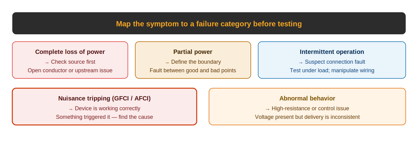
Once the issue has been reproduced, categorize it precisely. The failure category you observe immediately narrows the list of likely causes and points toward the right testing approach. Diagnosing before categorizing is like treating a patient before knowing the symptom — possible to get lucky, but not systematic.
The Five Categories
- Complete loss of power. Everything on the circuit is dead simultaneously. The fault is at the source or very early in the path — a tripped breaker, a failed breaker, a tripped GFCI that protects the whole circuit, or an open at the first device in the chain. Start at the source.
- Partial loss of power. Some devices on the circuit work and others don’t. The fault is between the last working device and the first dead one. The boundary is already partially defined — your job is to find the exact break point in that section.
- Intermittent operation. The circuit works sometimes and fails under specific conditions. This is almost always a connection fault — a backstabbed receptacle, a loose wire nut, or an undertorqued terminal that makes and breaks based on load, temperature, or vibration. Test under load; use the wiggle test at suspect connections.
- Nuisance tripping. A GFCI or AFCI trips repeatedly. The device is working correctly — something is triggering it. Do not reset and ignore. Do not replace the device with a standard breaker. Find the fault condition that is causing the trip: a ground fault in the wiring or a connected device, or an arc fault somewhere in the circuit.
- Abnormal behavior. Voltage is present and the device operates, but not correctly — lights dim under load, motors run slowly, devices produce reduced heat. This is the signature of a high-resistance connection in the path or a source voltage problem. Test under load; compare hot-to-neutral with hot-to-ground; check for voltage drop across the path.
Why Category Matters Before Testing
Each category points to a different part of the circuit and a different testing approach. A complete loss suggests source testing first. A partial loss suggests binary search in the affected section. A nuisance trip suggests isolation of loads and wiring sections. Starting with the wrong approach for the category wastes time even when the individual tests are performed correctly.
Spend 60 seconds categorizing before opening the first box. It costs nothing and consistently shortens the diagnostic path.
Identifying the Scope of the Problem
After defining the failure category, determine how much of the system is affected. The boundary between what works and what does not is one of the most valuable pieces of information in the entire diagnostic process — it tells you immediately where in the circuit the fault must be located.
Checking Adjacent Devices
A single dead outlet does not mean the circuit is dead. Check every outlet and device on the same circuit. If only one outlet is dead in a chain of five, the fault is between that outlet and the last working one — a very specific location. If all outlets on the circuit are dead, the fault is at the source or at the very beginning of the circuit run.
Steps for scope identification:
- Test every outlet on the affected circuit with a simple plug-in tester or lamp.
- Check outlets in adjacent rooms — circuits often run through multiple rooms and the labeling may not reflect this accurately.
- Test any other devices on the circuit: fixtures, switches, appliances.
- Check whether any GFCI receptacles on the circuit are protecting downstream outlets — a tripped GFCI can take out multiple outlets and fixtures that aren’t obviously connected to it.
- Ask whether any other unrelated circuits seem affected — multiple circuits failing simultaneously suggests a panel issue, a tripped main breaker, or a utility problem.
The Boundary Is the Answer
When you know the boundary — the last working point and the first failed point — you have already located the fault to a specific section of the circuit. Everything before the boundary is confirmed working. Everything at and after the boundary needs investigation. You only need to open and inspect the section between those two points.
Example: five outlets on a circuit. Outlets 1 and 2 work. Outlet 3 is dead. Outlets 4 and 5 are dead. The fault is between outlet 2 (last good) and outlet 3 (first bad). You open outlet 3, find a loose wire nut in the back of the box, and the repair is done. Without identifying the boundary, you might have opened all five outlets.
GFCI Protected Circuits
GFCI receptacles can protect downstream outlets and fixtures that are wired to their LOAD terminals. These downstream devices may be in completely different locations — a GFCI in the bathroom often protects outdoor outlets, garage outlets, and sometimes outlets in other bathrooms. If a group of seemingly unrelated devices are all dead, check every GFCI in the area and on the circuit — one tripped GFCI can look like a mysterious multi-location failure.
The boundary between working and non-working is not just a clue — it is the answer. Once you know the last working point and the first failed point, you have already located the fault to a specific section. Everything else is just confirming what you already know.
Confirming the Correct Circuit
Panel labeling is one of the least reliable sources of information in residential electrical troubleshooting. Labels are applied at original installation, often by workers under time pressure, and rarely updated when circuits are modified, extended, or repurposed. In older homes, the original labels may have been written in pencil and are now illegible, replaced with incorrect labels by previous owners, or simply wrong from the beginning.
Never trust a panel label to confirm the correct circuit. Always verify physically before beginning work.
The Verification Sequence
- Identify the candidate breaker based on the panel label and location of the fault.
- Turn the breaker off and confirm loss of power at the affected device. Use a meter or plug-in tester — not just an NCVT, which can produce ghost voltage readings on de-energized conductors adjacent to live ones.
- Note which other devices lose power when the breaker is off. This reveals the circuit’s actual coverage, which may be very different from the panel label. Write it down.
- Restore the breaker and confirm power returns to the affected area.
- Use a circuit tracer if the circuit layout is unclear, if multiple candidate breakers exist, or if you need to trace the circuit path through walls without opening them.
Common Panel Labeling Problems
- Multiple circuits sharing a label. “Kitchen” may cover three separate circuits on three separate breakers.
- Circuits that cross room boundaries. The “bedroom 2” circuit may include outlets in the hallway, one bathroom, and the guest room.
- GFCI-protected outlets not identified. The panel label shows a circuit breaker for “garage,” but the garage outlets are actually protected by a GFCI in the bathroom that also controls the outdoor receptacles.
- Multi-wire branch circuits. Two breakers sharing a neutral — turning off one breaker de-energizes only half the outlets on what looks like a single circuit.
- Added circuits with no label. A subsequent owner added a circuit for a workshop or hot tub and never updated the panel schedule.
Why This Matters for Safety
Working on the wrong circuit means working on what you believe is a de-energized circuit that is actually still energized. The conductors you open, the wires you handle, and the connections you touch are live. This is one of the most common causes of electrical accidents in residential service work — not ignorance of electrical hazards, but a false belief that a circuit has been de-energized when it has not.
The two-minute verification sequence is not bureaucracy. It is the step that confirms your personal safety before you touch anything.
Gathering Additional Clues
Once the problem is confirmed and the circuit is identified, gather additional context before moving to diagnosis. This information often dramatically shortens the subsequent diagnostic process by pointing immediately toward the most probable cause.
Timeline Questions
- When did it start? A sudden failure that occurred at a specific moment — “it was working at 9pm and dead at 9:15pm” — suggests a different mechanism than a gradual degradation over weeks. Sudden failures often point to a mechanical event: a connection that finally gave out, a breaker that tripped and won’t reset, or a device that failed.
- Has it happened before? A recurring problem that has been temporarily resolved and returned points strongly toward an intermittent connection fault. Something that has never worked points toward an installation error.
- Is it getting worse over time? Progressive failures — flickering that started occasionally and now happens constantly, a circuit that worked fine under light loads but now fails under normal use — indicate a degrading connection that has reached a critical threshold.
Recent Work Questions
Any work performed on the electrical system in the period before the problem started is a high-priority suspect:
- New outlets or fixtures added to the circuit — a connection may have been disturbed during the addition.
- Panel work: breaker replacements, new circuit additions, or any work that involved operating inside the panel.
- Remodeling that required moving or extending circuits.
- Work by other trades: HVAC installation, plumbing, or carpentry that might have disturbed conductors in the wall.
- Any DIY work performed by the homeowner, regardless of what they say it involved.
Load and Condition Questions
- Does it happen under specific loads? Faults that appear only when a certain appliance runs point to load-triggered connection failures — the connection is marginal and fails when current demand increases.
- Does it happen at specific times? Evening failures in homes with electric heat or A/C suggest thermal cycling of conductors at connections that are too loose. Morning failures in cold climates may indicate temperature-dependent connection failures.
- Has anything new been added to the circuit? A new appliance, a space heater, or additional equipment that increased the circuit’s load may have pushed a marginal connection over the edge.
- Has there been any water intrusion? Water in a junction box, at an outdoor outlet, or in a conduit run can cause immediate GFCI trips and intermittent faults that appear and disappear as conditions change.
Using the Information
Clues gathered from these questions don’t replace testing — they direct it. A homeowner who mentions that the problem started right after they had a new dishwasher installed has just pointed you to the most likely fault location. A circuit that fails only when the air compressor starts has just told you the fault is almost certainly a high-resistance connection that collapses under high starting current. Let the context narrow your search before you open the first box.
Recognizing Red Flags
During the verification phase, certain observations indicate conditions that go beyond a simple circuit fault. These red flags require elevated caution and may indicate serious hazards that need to be addressed before any diagnostic work proceeds.
Visible Signs of Overheating
Discoloration on outlet covers, switch plates, or the outlets themselves — typically browning or blackening around the slots or terminals — indicates that significant heat has been generated at that location. This is not cosmetic damage. It means either a high-resistance connection has been arcing or a sustained overload condition has been occurring. Both are fire risks.
Melted plastic on devices, insulation that has changed color or texture, or the distinctive smell of burnt plastic or insulation in a box or panel all indicate the same thing: this circuit has been running hot, and the condition may have damaged wiring that is not visibly accessible.
Sounds
Buzzing or crackling sounds from an outlet, switch, light fixture, or panel are never normal. These sounds indicate electrical arcing — current jumping across a gap at a loose connection, damaged insulation, or failing device. Arcing inside a wall cavity is a fire hazard regardless of whether it has tripped a breaker or AFCI.
A faint hum from a transformer, dimmer, or motor is normal. Crackling, sizzling, or irregular buzzing is not. If a customer reports hearing sounds from the walls or panel, take it seriously.
Immediately Tripping Breakers
A breaker that trips instantly every time it is reset — before any load is applied, sometimes even before the handle reaches the full ON position — indicates a hard fault: a direct short circuit or a ground fault severe enough to immediately exceed the breaker’s trip threshold. This circuit should remain de-energized until the fault is located.
Do not repeatedly reset a breaker that trips immediately. Each reset sends a surge of current into a faulted circuit. If the fault involves a damaged conductor with exposed copper, repeated resets increase the risk of fire or of the conductor welding to an adjacent surface.
Evidence of Code Violations
Non-code-compliant wiring observed during verification — conductors with improper insulation, junction boxes buried in walls without access covers, circuits without proper grounding, conductors that are undersized for the load — indicates installation quality that may be present throughout the system. Work on systems with visible code violations carefully, because the problems you can see are often an indication of problems you cannot.
Warm or Hot Surfaces
Outlet covers, switch plates, or panel covers that are warm to the touch indicate either a high-resistance connection generating heat or a circuit that has been consistently overloaded. An outlet cover that is hot is an emergency condition — there may be an active arc fault inside the box.
The Correct Response to Red Flags
When any of these conditions are observed, the system should remain de-energized until the condition is assessed and addressed. This is not overcaution — it is the correct professional response to a genuine hazard. Document what you observe, communicate it clearly to the customer, and do not restore power until you have a clear understanding of the fault condition.
Common Mistakes in Verification
These mistakes are responsible for the majority of extended troubleshooting times and incorrect repairs in the field. Recognizing them is the first step to avoiding them.
| Mistake | Why It Matters | The Correct Practice |
|---|---|---|
| Accepting the customer’s description without personal observation | Leads to diagnosing the wrong problem. Customer descriptions are filtered through non-technical understanding and may be incomplete or misleading. | Personally observe and reproduce the fault under the conditions that cause it before beginning diagnosis. |
| Skipping scope identification | Missing the boundary between working and non-working sections means missing the most useful diagnostic information available. Opens the wrong boxes. | Test every device on the affected circuit before beginning path diagnosis. Establish the last good point and first bad point. |
| Assuming panel labels are correct | Can result in working on an energized circuit believed to be de-energized. Most common cause of electrical shock in service work. | Always physically verify: turn off the candidate breaker and confirm loss of power at the work location with a meter. |
| Failing to check GFCI protection status | A tripped GFCI that protects multiple downstream outlets looks like a circuit failure. Missing it means diagnosing a problem that is already solved. | Check all GFCIs on the circuit and in adjacent locations before beginning any other diagnosis. A tripped GFCI should be the first thing ruled out. |
| Ignoring intermittent problems because they can’t be reproduced | Intermittent connection faults get worse over time and become permanent failures — or fire hazards — if not addressed. | Gather triggering condition information. Test under representative loads. Inspect high-probability failure locations even without reproducing the fault. |
| Misidentifying the failure category | Points the entire diagnostic process in the wrong direction. A misidentified nuisance trip treated as a complete loss of power leads to path testing when the protection device needs investigation. | Categorize the failure precisely: complete loss, partial loss, intermittent, tripping, or abnormal behavior. Each points to a different diagnostic approach. |
A well-verified problem is already halfway solved. The technician who takes three minutes to define the fault precisely before testing will locate it faster and repair it correctly the first time. The technician who starts testing without a clear definition of the problem is working in the dark.