The Purpose of Isolation
Isolation is the process of narrowing the fault location to a specific section of the circuit by systematically removing sections from consideration. It is the step that makes diagnosis efficient rather than exhaustive — instead of inspecting every connection point, you use measurement to eliminate entire sections until only the fault section remains.
What Isolation Is Not
Isolation is not trial-and-error replacement. Swapping devices and connections until something fixes the problem is the absence of isolation — it produces repairs without diagnosis, callbacks when the root cause is not found, and no improvement in the technician’s knowledge of the system. Isolation produces a specific, confirmed fault location before any repair is made, so that the repair addresses the actual problem rather than a guess about the problem.
Isolation is also not the same as the full four-element diagnostic process. By the time you reach the Isolation step, you have already confirmed the source, tested the load, and verified control conditions. Isolation applies specifically to path faults — the wiring and connection segment between the confirmed source output and the confirmed-dead load location.
Prerequisites for Effective Isolation
Isolation produces reliable results only when the preceding steps have been completed:
- Source confirmed. You have measured 120V stable under load at the breaker output. The search area starts downstream of the confirmed source.
- Failure boundary established. You know which devices are working and which are dead. This defines the section to be isolated.
- Control conditions verified. All switches are in correct positions, GFCIs are reset, sensors are triggered. The fault is in the physical wiring, not in a control state.
- Load tested or eliminated. The devices themselves are not the problem, or at least one confirmed substitute load has also failed at this location.
Skipping any of these steps and going directly to isolation means you may spend significant time isolating a section that is not the fault area because an unverified boundary assumption was wrong.
Isolation Techniques by Fault Type
The specific isolation technique depends on the fault category identified in the Verify step:
- Dead circuit (complete loss): Binary search — test for voltage presence/absence at midpoints, progressively halving the search area until the fault is confined between two adjacent accessible test points.
- Tripping GFCI or AFCI: Two-stage isolation — first separate loads from wiring, then binary search the wiring if the trip persists with no loads connected.
- High-resistance fault (abnormal behavior): Load testing at progressive midpoints — measure voltage under load at each point, looking for the transition from acceptable voltage to unacceptable voltage drop.
- Intermittent fault: Wiggle test under load — apply load, test at suspect locations, physically manipulate wiring at each potential connection fault while monitoring the load.
The Isolation Principle
The Isolation Principle is the foundation of all fault localization:
This principle is absolute. Once you have confirmed power is present at one point and absent at another, the fault is definitively located between those two points. You do not need to search outside this boundary. You do not need to re-verify points that have already been confirmed.
Establishing the Boundaries
Boundaries must be confirmed by measurement — not assumed:
- Known-good point: A location where you have personally measured correct voltage (hot-to-neutral approximately 120V, stable under load) and/or confirmed a device operates normally.
- Known-bad point: A location where you have personally measured no voltage, or measured voltage that collapses under load, or confirmed a device fails to operate despite correct voltage being applied.
Maintaining Boundary Accuracy
Boundaries can be invalidated by incomplete testing:
- A no-load voltage reading that appears normal but collapses under load is not a true confirmed-good boundary. Verify under load for any high-priority boundary points when intermittent behavior or high-resistance connections are suspected.
- A device that is dead may be dead because it is fed from the LOAD terminals of a tripped GFCI — not because the circuit is open at that point. Confirm that the power absence is due to the path, not to a control device state that could be changed.
Moving the Boundaries
Each isolation test moves one boundary:
- Find voltage at a new point between the current good boundary and the bad boundary → move the good boundary to this point.
- Confirm absence of voltage at a new point between the current good and bad boundaries → move the bad boundary to this point.
- When the two boundaries are adjacent (consecutive devices or connection points), the fault is between them. Open and inspect that specific section.
This is the complete algorithm of fault isolation. It is simple in principle and powerful in practice. Apply it consistently and you will locate every path fault in the minimum number of steps.
Why the Principle Is Absolute
The Isolation Principle has no exceptions because it is a logical necessity, not a heuristic or rule of thumb. If power is present at Point A and absent at Point B, and the circuit path runs from A through a section of wiring to B, the break in that path is in the wiring section between A and B. It cannot be elsewhere — a fault outside this section would not produce this specific pattern of working-at-A, dead-at-B.
This logical certainty is what makes isolation so powerful. You are not estimating the most likely fault location — you are eliminating everything outside the boundaries with certainty. Every point you have confirmed working cannot be the fault. Every section you have confirmed functioning cannot contain the fault. What remains after elimination is the fault, and only the fault.
The Danger of Assumption Creep
The most common way the Isolation Principle is violated is through assumption creep — allowing unconfirmed assumptions to function as confirmed boundaries. This happens gradually and often unconsciously:
- “The source is fine — I can see the breaker is on and the panel looks normal.” This is an assumed boundary. An assumed boundary is not a confirmed boundary.
- “The problem must be in this section — the customer said all the trouble started here.” The customer’s statement is an observed clue, not a confirmed boundary.
- “The meter showed 120V at that outlet earlier, so that section is good.” A reading from earlier is only as valid as the conditions under which it was taken. A no-load reading on a circuit with an intermittent fault may not reflect the current state.
Each of these assumptions, if wrong, sends the diagnosis into the wrong section of the circuit. The discipline of confirming every boundary by measurement — not by assumption, observation, or recall — is what keeps isolation reliable.
Using the Principle on Complex Circuits
On circuits with branches, the Isolation Principle applies to each branch independently. A junction point where the circuit splits into two branches has two downstream sections to isolate. Apply the principle to each branch separately: which branch has power, and which does not? The branch without power has a fault in its section. The other branch is cleared. This decomposition handles any circuit topology because it reduces any complex circuit to a series of simple source-to-load sections, each of which can be isolated independently.
Similarly, on circuits with multiple control devices in series — a switch feeding a GFCI feeding a load — the Isolation Principle applies to each control device’s LINE and LOAD terminals as test points. Work through the control devices in sequence: power at LINE of the first device, power at LOAD of the first device, power at LINE of the second device, power at LOAD of the second device. The first point where power is absent in sequence is the location where the break or control interruption is occurring.
Applying the Principle Across the Full Diagnostic Process
The Isolation Principle is not unique to the Path step — it is the underlying logic of the entire eight-step diagnostic process. At the course level:
- Confirming the source good establishes a boundary: the fault is downstream of the source. Everything upstream is eliminated.
- Testing the load and finding it functional establishes another boundary: the fault is not at the load. The load is eliminated.
- Verifying control conditions establishes a third boundary: the fault is not in an unsatisfied enabling condition. Control conditions are eliminated.
By the time you reach the Isolation step, you have already established three boundaries through the preceding steps. What remains is the path — the wiring and connections between the confirmed source output and the confirmed dead load. The Isolation Principle then applies within this already-narrowed section to identify the specific fault point.
This is why the full eight-step process is efficient rather than redundant. Each step narrows the search area by eliminating an entire category of potential fault location. Isolation within the path section then narrows it further to a specific section of wiring. By the time you open the first box, you know which box to open.
Isolation for Tripping Circuits (AFCI/GFCI)
When a protective device trips, the isolation process has one goal: determine whether the fault that caused the trip is in a connected load or in the wiring itself. This distinction is critical because the two conditions require completely different responses — and one of them (a fault in the wiring) is a safety issue that must be resolved before the circuit can be safely re-energized.
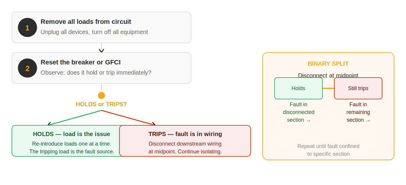
The Two-Stage Isolation Protocol
Stage 1: Isolate loads from wiring.
- Unplug and disconnect every load from the affected circuit — every device plugged into every outlet, every hardwired load turned off at its local disconnect if possible.
- Reset the protective device (GFCI or AFCI breaker).
- Observe: does it hold, or does it trip again?
- Holds with no loads: The fault is in one of the loads, not in the wiring. The wiring is safe. Proceed to Stage 2.
- Trips with no loads: The fault is in the wiring. Do not re-energize the circuit until the wiring fault is located and corrected. Proceed to binary search of the wiring.
Stage 2: Identify which load is the fault source (if Stage 1 held).
- With the device reset and holding, reintroduce loads one at a time.
- After adding each load, wait 30 seconds and observe.
- When the device trips, the last load added is the fault source.
- Confirm by removing that load and resetting — the device should hold with all other loads connected.
Binary Search of the Wiring (When Stage 1 Trips)
If the protective device trips with no loads connected, the fault is in the wiring between the panel and the last outlet in the circuit. Use binary search to isolate:
- Disconnect the downstream wiring at the midpoint of the circuit — at a junction box or the back of an outlet at approximately the halfway point.
- Reset the protective device.
- If it holds: fault is in the disconnected (downstream) section.
- If it still trips: fault is in the remaining connected (upstream) section.
- Continue halving the search area until the fault section is two adjacent connection points.
- Inspect that section: look for staples through cables, pinched conductors, insulation damage, or conductor-to-conductor contact.
Isolation for AFCI vs. GFCI — Key Differences
The isolation sequence is the same for both device types, but the fault characteristics are different:
- GFCI faults are current-to-ground leakage paths — moisture, damaged insulation, neutral-to-ground contact. They are often present all the time once they develop and will trip the GFCI reliably every time the fault condition exists.
- AFCI faults are arcing conditions that may be intermittent — appearing only under specific load conditions, vibration, or temperature. An AFCI fault that is not present when you test may appear when the circuit is loaded with the specific device or combination of conditions that triggered the original trip. Test under the same conditions that originally caused the trip.
Interpreting Isolation Results
When a section of wiring is disconnected or a load is removed during isolation, the result tells you exactly where to focus next. Interpreting results correctly prevents backtracking and keeps the diagnosis moving forward.
For Tripping Circuits — The Two Outcomes
| After isolating a section or load | Conclusion | Next step |
|---|---|---|
| Device resets and holds | Fault is in the disconnected section or the removed load | If load removed: reconnect loads one at a time to identify the specific fault source. If wiring disconnected: inspect that section physically. |
| Device trips again on reset | Fault is in the remaining connected section | Divide the remaining section in half. Disconnect at the midpoint and repeat. |
| Device behavior is inconsistent (sometimes holds, sometimes trips) | Intermittent fault — may be in the disconnected section, the connected section, or both | Apply the specific load or condition that originally triggered the trip. Test under that specific condition before concluding which section is clear. |
For Dead Circuits — Binary Search Results
| Voltage at midpoint | Conclusion | Boundary update |
|---|---|---|
| ~120V (present) | Midpoint is good. Fault is downstream. | Move known-good boundary to this midpoint. Select new midpoint in downstream half. |
| 0V (absent) | Midpoint is bad. Fault is upstream. | Move known-bad boundary to this midpoint. Select new midpoint in upstream half. |
| Present at no load, absent under load | High-resistance connection upstream — midpoint is bad under real conditions. | Use loaded result. Move bad boundary to this midpoint. Search upstream half. |
When Results Don’t Follow the Pattern
Occasionally isolation produces results that don’t fit the expected pattern — the circuit holds in some configurations but trips in others in ways that seem contradictory, or voltage appears on one side of what should be an open break. These situations usually have one of three causes:
- Multiple fault points. A circuit with two separate faults produces confusing isolation results because fixing one fault changes which section the remaining fault appears in. When results are contradictory, consider the possibility of multiple faults and approach each section independently.
- Fault is not in the path. Source, load, or control fault that was not fully verified before beginning isolation. If isolation results don’t make sense, re-verify the source and re-check control conditions before continuing.
- Intermittent fault not consistently triggered. The test conditions are not reproducing the fault condition. Identify the triggering condition more precisely and reproduce it during testing.
When results don’t make sense, stop and re-evaluate rather than testing further on what may be an incorrectly defined search area. A moment of review almost always identifies the source of the confusion more quickly than continued testing does.
Common Isolation Mistakes
Isolation mistakes cause more extended diagnostic sessions than almost any other type of error. Each one is avoidable with consistent discipline.
| Mistake | What Goes Wrong | The Correct Practice |
|---|---|---|
| Disconnecting multiple sections at once | Cannot determine which disconnection caused the change in fault behavior. Results are ambiguous and require reconnecting everything and starting again. | Disconnect one section. Test. Record the result. Then proceed to the next section. One change per test, always. |
| Failing to test after each change | May have already passed the fault location without knowing it. Multiple changes without testing create ambiguous results. | Test after every individual change. Record the result before making the next change. |
| Replacing components instead of isolating | If the replacement fixes the problem, the root cause is confirmed but not understood. If it doesn’t fix it, you have added cost and time without gaining information. | Isolate the fault to a specific section first. Then inspect and repair the confirmed fault location. Replacement is a repair action, not a diagnostic one. |
| Treating assumed boundaries as confirmed | The search area is incorrectly defined. May spend significant time in the wrong section of the circuit. | Boundaries are established by measurement, not assumption. Verify the source, verify the first bad point, and confirm adjacent points before narrowing the search area. |
| Re-testing already confirmed good sections | Wastes time and can introduce confusion about what has and hasn’t been established. | Keep track of confirmed good and bad points. Only test within the current search area — between the established boundaries. |
| Not isolating under load for load-triggered faults | High-resistance connections pass no-load tests but fail under current. Isolation results at no load appear to eliminate the fault section incorrectly. | For suspected high-resistance faults, test under load at each isolation point. Use the loaded result, not the no-load result, to establish boundaries. |
Isolation is not about working harder — it is about working more precisely. Each change should answer exactly one question. When the answer to that question determines your next move, you are isolating correctly and diagnosis is efficient.
Building the Isolation Habit
Isolation is a skill that improves with deliberate practice. Early in a technician’s development, isolation can feel slow — it requires stopping before opening a box, taking a measurement, recording the result, and then deciding where to go next rather than simply going to the most likely-looking location. This deliberateness is not inefficiency; it is the process that ensures you don’t miss the fault by opening the wrong boxes first.
With practice, the isolation process becomes faster without becoming less disciplined. An experienced technician performing binary search on a 10-outlet circuit will take 3 measurements, confirm the fault to a 2-outlet section, and open one specific box — all in under 10 minutes. A less experienced technician working by intuition might open 4–5 boxes at random before finding the fault. The experienced technician opened fewer boxes and took less total time, not because they skipped isolation but because they performed it fluently.
To build this fluency: practice stating your expected result before every measurement. “I expect power here because this point is between the confirmed source and the midpoint I’m about to test.” If your expectation is wrong, stop and understand why before proceeding. This habit of expectation-and-comparison is the cognitive mechanism that makes each test diagnostic rather than exploratory.
Isolation in the Field — Practical Constraints
In the field, ideal binary search midpoints are not always accessible. Junction boxes may be in walls. Outlet boxes may be behind furniture. Circuits may run through attics or crawl spaces with limited access. In these situations, the isolation principle still applies — you simply work with the accessible test points that are available.
When the ideal midpoint is not accessible, choose the next-best accessible point. A test at the 3rd outlet in a 10-outlet chain when the 5th outlet is behind a built-in is still more efficient than sequential testing from the beginning. The fault area is still progressively narrowed even if the boundary movements are not perfectly binary.
When a fault is definitively isolated to a section that has no accessible intermediate test points, the only option is physical inspection of the wiring in that section. This may require opening a wall section or accessing an attic or crawl space. The isolation work that preceded this step ensures you are opening only the specific section that contains the fault — not opening walls in multiple locations based on guesses.
Isolation on Circuits with Limited Access
Ideal isolation requires accessible test points at regular intervals throughout the circuit. In practice, some circuits have long runs with limited accessible midpoints — a circuit that runs from a panel through a finished wall to a single outlet in a distant room may have only two accessible test points: the panel and the outlet. In this situation, the binary search method degrades to a single test, but the underlying principle still applies: if power is present at the panel output and absent at the outlet, the fault is in the wiring between those two points.
When access is limited, the inspection of the fault section may require opening walls. Before doing so, narrow the search area as much as possible using whatever accessible points exist — any outlet, switch, or junction box on the circuit. Even reducing the search area from “the entire circuit” to “the section between the last outlet before the dead stretch and the dead outlet” is meaningful — it tells you which wall section to open rather than guessing.
Documentation During Isolation
As isolation proceeds, maintain a running record of confirmed-good and confirmed-bad boundaries. Even a simple handwritten list — “G = outlet 3, B = outlet 4” — is enough to maintain orientation during a complex isolation sequence. This record prevents re-testing confirmed points, avoids confusion about which half of the circuit is currently being searched, and provides context if the job is interrupted and resumed.
For multi-fault circuits or circuits with complex layouts, a rough sketch with test results marked at each point is worth the 2 minutes it takes to draw. The sketch becomes the documentation for the job record and the communication tool for explaining the diagnosis to the customer.